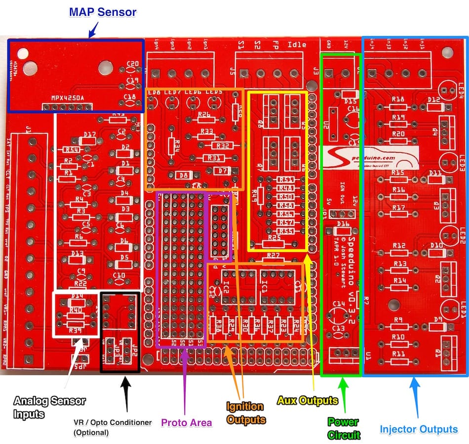
The first widely available project shield targets many one- to four-cylinder port-injected engines. The project documents four injector and four ignition outputs, CLT, IAT, TPS and oxygen inputs, an optional crank/cam VR conditioner mount, MAP location and four medium-current spare outputs. Connections use screw terminals and a prototyping area permits additional circuits.
Pinouts and revisions
Use the v0.3 board manual, connector layout and revision list. Its firmware mapping table is explicitly numbered in Arduino Mega pins, not screw-terminal or IDC connector positions. The official board files provide hardware designs. Verify build and jumper setup; logic ignition outputs require appropriate coil drivers.
Confirm exact assembled revision, modifications, controller and firmware before wiring. Sensor conditioning and compatible drivers matter; see project hardware requirements.
v0.3.2 screw-terminal layout
The official v0.3.2 PCB drawing labels the following terminals. Positions are ordered as drawn, not official numbered cavities; check the board silkscreen and original drawing. This table is specifically for v0.3.2, and other revisions or builds may differ.

J1 sensor and trigger terminals (left to right in source PCB drawing)
| Position in cited drawing | PCB label |
|---|---|
| 1 | IAT |
| 2 | IAT Ret |
| 3 | CLT |
| 4 | CLT Ret |
| 5 | TPS |
| 6 | TPS Ret |
| 7 | Vref |
| 8 | O2 |
| 9 | GND |
| 10 | Vref |
| 11 | VR1− |
| 12 | RPM1 |
| 13 | VR2− |
| 14 | RPM2 |
J2 injector terminals (top to bottom)
| Position in cited drawing | PCB label |
|---|---|
| 1 | INJ1 |
| 2 | INJ2 |
| 3 | INJ3 |
| 4 | INJ4 |
J3 power terminals (top to bottom)
| Position in cited drawing | PCB label |
|---|---|
| 1 | 12 V |
| 2 | GND |
J5 auxiliary terminals (top to bottom)
| Position in cited drawing | PCB label |
|---|---|
| 1 | Idle |
| 2 | FP |
| 3 | S2 |
| 4 | S1 |
J4 ignition terminals (top to bottom)
| Position in cited drawing | PCB label |
|---|---|
| 1 | IGN1 |
| 2 | IGN2 |
| 3 | IGN3 |
| 4 | IGN4 |
For firmware from January 2017 onward, the project manual gives defaults of S1 for VVT, S2 for boost, FP for fuel pump and Idle for idle 1; these can be configured. The manual explains that ignition outputs drive a logic-level igniter or coil and must not directly drive a high-current coil. Trigger jumpers and optional conditioners depend on the sensor type.