Tuning Wiki
Applies to

Check the hardware and software limits stated in this article.

Speeduino v0.1 PCB design drawing
Speeduino v0.1 PCB design drawing by Josh Stewart. Source: Speeduino hardware repository; distributed under the repository's CERN-OHL-S licence.

The v0.1 was the first hardware implementation, an Arduino Mega shield intended for stationary testing rather than general in-car use. The project describes four fuel and four ignition channels and identifies limitations including a single sensor-ground screw terminal, no built-in VR conditioning and no onboard bias resistors for the two temperature inputs.

Connections and design

The historic v0.1 board description and layout is the model-specific source; it is a prototype design, not the later v0.3 or v0.4 connector layout.

Confirm exact assembled revision, modifications, controller and firmware before wiring. Sensor conditioning and compatible drivers matter; see project hardware requirements.

v0.1 prototype terminal labels

The following labels appear on the project's Kartduino v0.1 PCB drawing, ordered as pictured rather than as numbered cavities. This early prototype was for stationary testing; it has limited grounding and no onboard VR conditioning or temperature-input bias resistors. Verify the actual build and consult the v0.1 project notes.
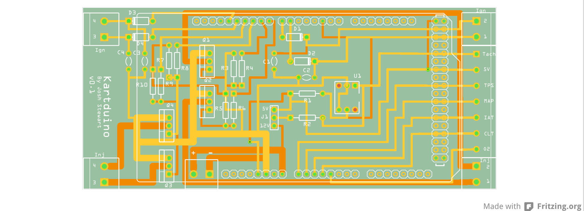
Ignition, left side (top to bottom)

Position in drawingBoard label
1IGN 4
2IGN 3

Ignition, right side (top to bottom)

Position in drawingBoard label
1IGN 2
2IGN 1

Sensor terminals, right side (top to bottom)

Position in drawingBoard label
1Tach
25 V
3TPS
4MAP
5IAT
6CLT
7O2

Injector, left side (top to bottom)

Position in drawingBoard label
1INJ 4
2INJ 3

Injector, right side (top to bottom)

Position in drawingBoard label
1INJ 2
2INJ 1

Power terminal pair (left to right)

Position in drawingBoard label
1+
2−