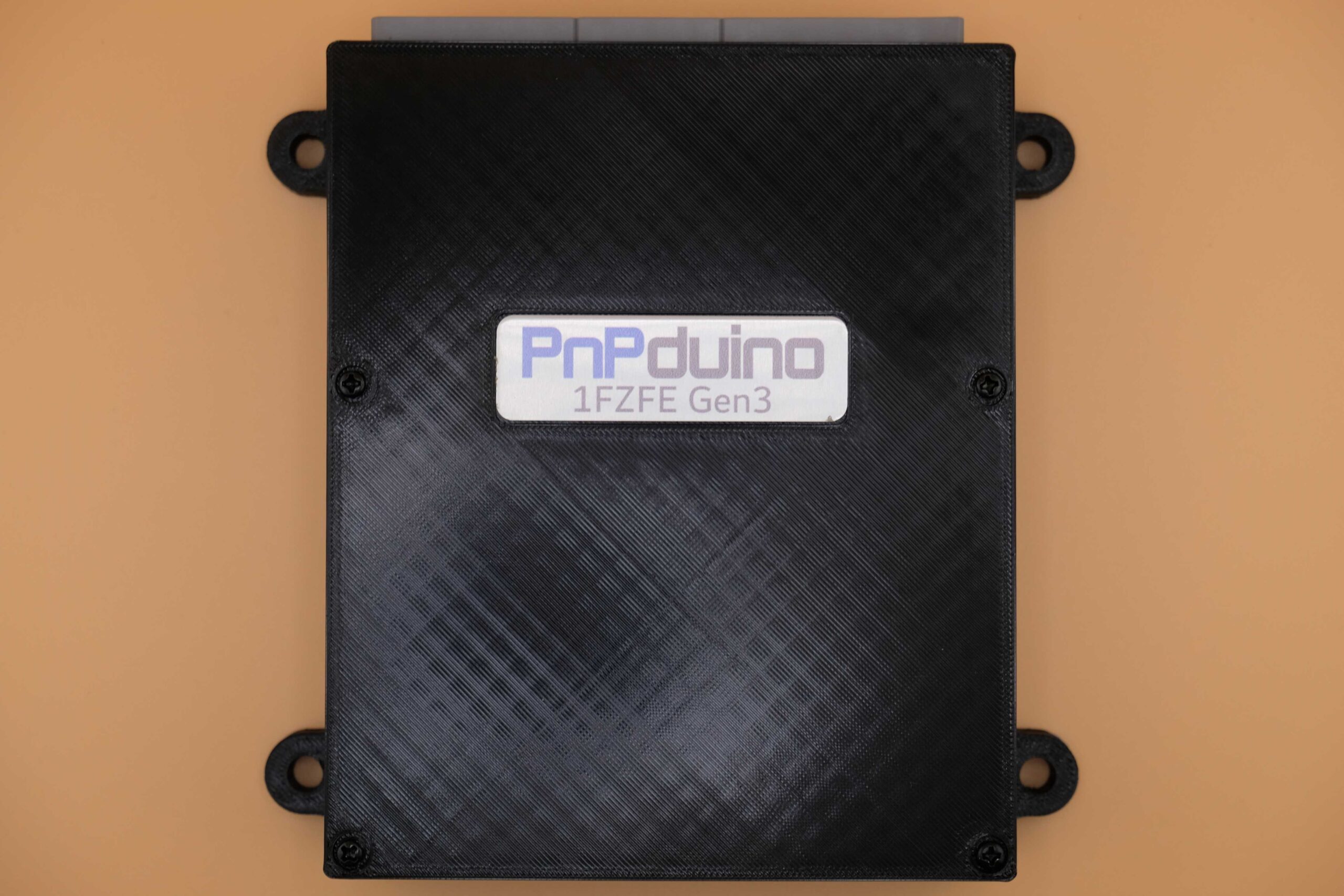
PnPduino Toyota 1FZ-FE Gen3 is a PnPduino programmable engine-management ECU. Manufacturer product information.
Application and identification
Plug-in for the manufacturer's 2003–2007 4.5-litre Toyota Land Cruiser 1FZ-FE Gen3 application, manual transmission only. The vehicle has four plugs, of which the unit uses the 26-, 16- and 22-position plugs. Gen3 and Gen2 pinouts differ, despite the common used connector counts.
System and wiring
A JDM VR conditioner is fitted. The manufacturer describes semi-sequential injection and wasted-spark ignition, stock MAP sensing, and support for high- or low-impedance injectors. An aftermarket wideband controller is required for proper tuning.
Connector identification
| Connector | Manufacturer description | Scope |
|---|---|---|
| Used vehicle connector | 26 positions | Gen3 application; do not substitute Gen2 assignments |
| Used vehicle connector | 16 positions | Gen3 application; do not substitute Gen2 assignments |
| Used vehicle connector | 22 positions | Gen3 application; do not substitute Gen2 assignments |
| Fourth vehicle connector | Not used by this ECU per manufacturer | Position count not specified in the product listing |
The manufacturer’s numbered Gulf-region connector schedules are transcribed below. C3 is shown on the diagram but not identified in its source table, and B2 and B16 share a source row; check the exact loom and manufacturer diagram.
Software and calibration
This listing specifies official Speeduino firmware and use of the SpeedyLoader INI; check the actual build and manufacturer guidance. A supplied base map needs final tuning.
See the PnPduino manufacturer index.
Manufacturer connector assignments
The source labels this diagram for Gulf-country 1FZ-FE Gen3 and views the front of the male ECU connector. Its labels and model-specific hardware differ from the other generation. B2 and B16 share one source row; C3 is pictured but is absent from the source table and is marked accordingly here. Original-vehicle labels, PnPduino assignments and TunerStudio pin numbers are different columns; do not treat an OEM label as evidence of an active ECU connection. Source: PnPduino 1FZ-FE Gen3 pinout. Blank cells reflect the original schedule, not a declaration that the position is spare. The original uses colour to distinguish retained vehicle, unused vehicle and added PnPduino signals; check the original drawing and exact regional loom before wiring.
Connector B
| ECU pin | 1FZ label | 1FZ description | PnPduino connection | PnPduino function | TunerStudio pin | Remarks |
|---|---|---|---|---|---|---|
| B13 | E01 | Power Ground | ||||
| B26 | E02 | Power Ground | ||||
| B12 | INJ1/5 | Injector 1 and 5 | INJ1 | Injector 1 | 8 | |
| B25 | INJ3/6 | Injector 3 and 6 | INJ2 | Injector 2 | 7 | |
| B11 | INJ2/4 | Injector 2 and 4 | INJ3 | Injector 3 | 6 | |
| B24 | INJ4 | Injector 4 | 5 | |||
| B10 | RSD | Rotary ISCV | IDLE1 | Idle 1 | 9 | |
| B23 | ||||||
| B9 | FAN | Radiator Fan | 24 | Not used by default | ||
| B22 | LC3 | Low Current 3 | 28 | |||
| B8 | ||||||
| B21 | LC2 | Low Current 2 | 27 | |||
| B7 | IGT1 | Igniter 1 and 5 | IG1 | Ignition 1 | 35 | |
| B20 | IG4 | Ignition 4 | 34 | Not used by default | ||
| B6 | IGT2 | Igniter 3 and 6 | IG2 | Ignition 2 | 36 | Not used by default |
| B19 | G2 | CAM signal | VR2+ | VR2+ | 18 | from CAM Sensor |
| B5 | IGT3 | Igniter 2 and 4 | IG3 | Ignition 3 | 33 | |
| B18 | NE+ | CRANK signal | VR1+ | VR1+ | 19 | from CRANK Sensor |
| B4 | ||||||
| B17 | NE- | CAM/CRANK Ground | VR1- | VR1- | ||
| B3 | IGF | Ignition Confirmation | ||||
| B2 & B16 | 12VF | Fused 12V | Only for 12V Sensors | |||
| B15 | GRND | Sensor Ground | Only for 12V Sensors | |||
| B1 | IDLE2 | Idle 2 | 10 | Can be used for High Output | ||
| B14 | E1 | Engine Ground |
Connector A
| ECU pin | 1FZ label | 1FZ description | PnPduino connection | PnPduino function | TunerStudio pin | Remarks |
|---|---|---|---|---|---|---|
| A8 | TC | Data Link | ||||
| A16 | VVT | VVT | 11 | Can be used for High Output | ||
| A7 | VAF | Variable Resistor | ||||
| A15 | FPR | Fuel Pump Resistor | ||||
| A6 | CANL | CAN Lo | If STM32 is used | |||
| A14 | CANH | CAN Hi | If STM32 is used | |||
| A5 | KNKL | Knock Sensor Left | KNOCK | Knock | 21 | Not used by default, for future use |
| A13 | KNKR | Knock Sensor Right | FLEX | Flex sensor | 2 | Not used by default |
| A4 | THW | Coolant Temperature | CLT | Engine Coolant Temp | A4 | |
| A12 | ||||||
| A3 | THA | Intake Air Temperature | IAT | Intake Air Temp | A5 | |
| A11 | VTA | Throttle Position Sensor | TPS | Throttle Position Sensor | A3 | |
| A2 | PIM | MAP sensor | MAP | MAP sensor | A0 | |
| A10 | SIL | Data Link | ||||
| A1 | VC | 5V Sensor Supply | 5V | 5V from ECU | Fused 5V to sensors | |
| A9 | E2 | Sensor Ground |
Connector C
| ECU pin | 1FZ label | 1FZ description | PnPduino connection | PnPduino function | TunerStudio pin | Remarks |
|---|---|---|---|---|---|---|
| C11 | STA | Starter Switch | ||||
| C22 | NSW | Neutral Switch | CLUTCH | Clutch switch | 37 | |
| C10 | A/C1 | AC Amplifier | INP2 | Input 2 | A9 | AC Switch to Idle Up |
| C21 | ACT | AC Control | ||||
| C9 | SPD | Vehicle Speed | VSS | Vehicle Speed | 20 | |
| C20 | TACH | Tachometer Output | TACH | TACH Out | 22 | |
| C8 | FPM1 | Main Fuel Pump | Not used by default | |||
| C19 | FPM2 | Sub Fuel Pump | INP3 | Input 3 | A10 | Not used by default |
| C7 | FPMS | Fuel Tank Change Switch | INP6 | Input 6 | A12 | Not used by default |
| C18 | INP5 | Input 5 | A6 | |||
| C6 | IMO | Immobilizer | INP1 | Input 1 | A8 | |
| C17 | IMI | Immobilizer | INP4 | Input 4 | A11 | |
| C5 | W | Check Engine Light | FAN2 | Fan 2 | 25 | Not used by default, for future use |
| C16 | INP7 | Input 7 | A13 | |||
| C4 | FC | Circuit Opening Relay | FP | Fuel Pump | 23 | |
| C15 | FPR2 | Sub Fuel Pump Relay | LC1 | Low Current 1 | 26 | |
| C14 | FPLD | Sub Fuel Indicator Lamp | LC4 | Low Current 4 | 29 | |
| C3 | Position C3 is not listed in the manufacturer table | |||||
| C2 | STP | Stop Light | ||||
| C13 | BOOST | Boost | 12 | Can be used for High Output | ||
| C1 | BATT | Battery Constant 12V | Not used by default | |||
| C12 | +B | Ignition +12V switched | Should be fused 12V supply to ECU |