PnPduino Honda K-Series Swap is a PnPduino programmable engine-management ECU. Manufacturer product information.
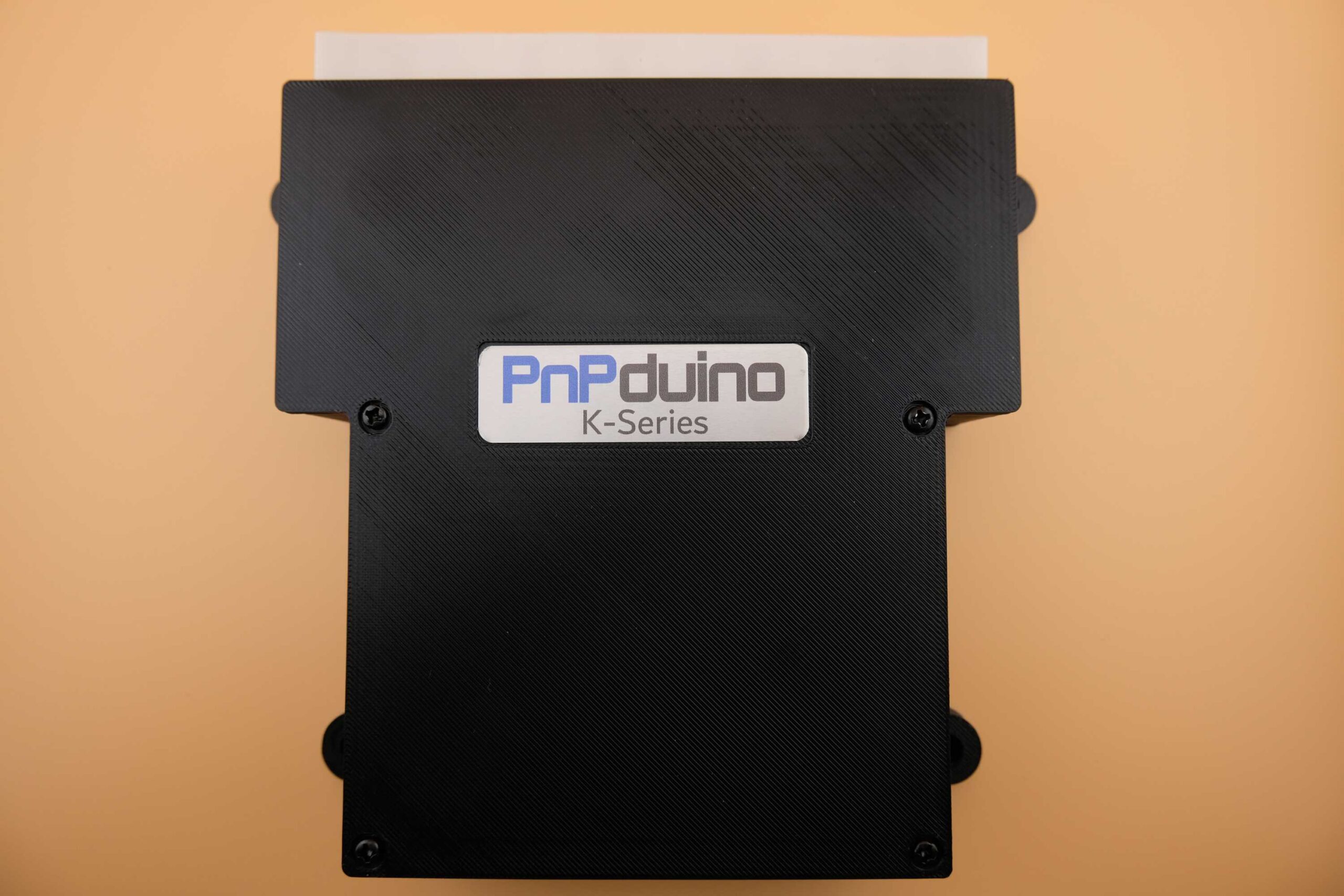
Application and identification
The manufacturer specifies K-series engine swaps using a 2002–2004 engine harness, cable throttle and manual transmission for standalone operation. A 2005–2006 harness needs a conversion adapter, and a 2002–2004 vehicle-speed sensor is required unless the later sensor is converted as instructed.
System and wiring
The supplier says factory OBD2, CAN and K-line functions are unavailable, limiting this application to K-swapped vehicles. VTC, VTEC and trigger inputs are supported; AC switch and tachometer require wiring. Automatic or drive-by-wire applications are described only as piggyback setups, not standalone transmission or electronic-throttle control.
A complete pin-by-pin ECU connector table has not been verified from the cited product information. Obtain the diagram for the exact model and revision from PnPduino documentation; the vehicle ECU pinout and other PnPduino models must not be assumed interchangeable.
Software and calibration
Uses TunerStudio and supplier-installed custom firmware; the supplier says not to update it. OEM oxygen sensors are unsupported, and an aftermarket wideband and final tuning are required.
See the PnPduino manufacturer index.
Manufacturer connector assignments
The following schedule reproduces the shared K-Series/D17 manufacturer pinout, viewed from the front of the male ECU header. Pairs such as A2/A3 appear on one manufacturer row. B1 is marked unavailable on D17; read all model-specific remarks and the source colour legend. The source groups functions by firing order and notes that PnPduino channel numbers do not necessarily match cylinder numbers. Source: PnPduino Honda K-Series / D17 pinout. Blank cells reflect the original schedule, not a declaration that the position is spare. The original uses colour to distinguish retained vehicle, unused vehicle and added PnPduino signals; check the original drawing and exact regional loom before wiring.
Connector A
| Honda label | ECU pin | Honda function | PnPduino connection | PnPduino function | TunerStudio pin | Remarks |
|---|---|---|---|---|---|---|
| PHO2S HTC | A1 | AFR Sensor Heater Ctrl - | Not Used | |||
| IGP1/IGP2 | A2/A3 | Power Source | 12V | BATT | 12V Battery | |
| PG1/PG2 | A4/A5 | Power Ground | GRND | ECU Ground | Power Ground at the Head cover, not Chassis ground | |
| PHO2S+ | A6 | Oxygen Sensor + | O2 | Oxygen Sensor | A1 | Wideband O2 Sensor Linear Output |
| CKP | A7 | Crankshaft Sensor | HALL1 | Hall Sensor 1 | 19 | 12+1 Crankshaft sensor signal |
| IMRC | A8 | IMRC Valve Position Sensor | INP2 | Input 2 | A9 | Intake Manifold Runner Valve Position Sensor or Spare Input 2 |
| KS | A9 | Knock Sensor | HALL4 | Hall Sensor 4 | 21 | Spare Hall Sensor or Spare Input |
| SG | A10/A 11 | Sensor Ground | GRND | ECU Ground | Sensor Ground | |
| IACV | A12 | Idle Air Control Valve | IDLE1 | Idle 1 | 9 | Idle 1 |
| - | A13 | - | CLUTCH | Clutch | 37 | Clutch Switch Input |
| - | A14 | - | INP3 | Input 3 | A10 | Spare Input 3 |
| TPS | A15 | Throttle Pos sensr | TPS | Throttle Pos sensr | A3 | Throttle Position Sensor |
| PHO2S- | A16 | Oxygen Sensor - | GRND | ECU Ground | ECU Ground | |
| - | A17 | - | INP4 | Input 4 | A11 | Spare Input 4 |
| VSS | A18 | Vehicle Speed | VSS | Vehicle Speed | 20 | Vehicle Speed Sensor Input Low Frequency only |
| MAP | A19 | Manifold Abs Pres | MAP | Manifold Abs Pres | A0 | MAP Sensor |
| VCC | A20 /A21 | Sensor Voltage | 5V | 5V Supply | 5V Supply to Sensors | |
| PHO2S HTC+ | A22 | AFR Sensor Heater Ctrl + | Not Used | |||
| LG | A23 /A24 | Logic Ground | GRND | ECU Ground | Logic Ground | |
| CMP | A25 | Camshaft Position Sensor | HALL3 | Hall Sensor 3 | 3 | Intake Cam Sensor 4 pulses |
| TDC | A26 | Top Dead Center Sensor | HALL2 | Hall Sensor 2 | 18 | Exhaust Cam Sensor 4+1 pulses |
| IGPLS4 | A27 | Ignition Coil Pulse 4 | IG3 | Ignition 3 | 33 | In Firing order 1-3-4-2 (IG3 of PnPduino is actual IG4) |
| IGPLS3 | A28 | Ignition Coil Pulse 3 | IG2 | Ignition 2 | 36 | In Firing order 1-3-4-2 (IG2 of PnPduino is actual IG3) |
| IGPLS2 | A29 | Ignition Coil Pulse 2 | IG4 | Ignition 4 | 34 | In Firing order 1-3-4-2 (IG4 of PnPduino is actual IG2) |
| IGPLS1 | A30 | Ignition Coil Pulse 1 | IG1 | Ignition 1 | 35 | In Firing order 1-3-4-2 |
| - | A31 | - | INP1 | Input 1 | A8 | Spare Input 1 |
Connector B
| Honda label | ECU pin | Honda function | PnPduino connection | PnPduino function | TunerStudio pin | Remarks |
|---|---|---|---|---|---|---|
| VTC+ | B1 | VTC Oil Control + | 12V | BATT | 12V Battery (Not available for D17) | |
| INJ4 | B2 | Injector 4 | INJ3 | Injector 3 | 6 | In Firing order 1-3-4-2 (INJ3 of PnPduino is actual INJ4) |
| INJ3 | B3 | Injector 3 | INJ2 | Injector 2 | 7 | In Firing order 1-3-4-2 (INJ2 of PnPduino is actual INJ3) |
| INJ2 | B4 | Injector 2 | INJ4 | Injector 4 | 5 | In Firing order 1-3-4-2 (INJ4 of PnPduino is actual INJ2) |
| INJ1 | B5 | Injector 1 | INJ1 | Injector 1 | 8 | In Firing order 1-3-4-2 |
| FANC | B6 | Fan Control | FAN | Fan 1 | 24 | Thermo Fan |
| RVS | B7 | Reverse Lockout | LC2 | Low Current 2 | 27 | Low Current Output 2 |
| ECT | B8 | Engine Coolant Temp | CLT | Engine Coolant Temp | A4 | Engine Coolant Temp |
| VTPSW | B9 | VTEC Pressure Switch | Not Used | |||
| ALTL | B10 | Alternator Lamp | Not Used | |||
| - | B11 | - | ||||
| - | B12 | - | INP5 | Input 5 | A6 | Spare Input 5 |
| ALTF | B13 | Alternator Field | Not Used | |||
| LSA+ | B14 | A/T | Not Used | |||
| VTS | B15 | VTEC Solenoid | VVT | VVT | 11 | VTEC +12V output |
| LSB+ | B16 | A/T | CANL | CAN Lo | For STM32 Processor | |
| IAT | B17 | Intake Air Temp | IAT | Intake Air Temp | A5 | Intake Air Temp |
| ALTC | B18 | Alternator Control | LC4 | Low Current 4 | 29 | Low Current Output 4 |
| - | B19 | - | FLEX | Flex Fuel Sensor | 2 | Flex Fuel Sensor |
| - | B20 | - | BOOST | Boost Solenoid | 12 | Boost Control Solenoid |
| PCS | B21 | EVAP purge | Not Used | |||
| IMRC | B22 | IMRC Solenoid | LC3 | Low Current 3 | 28 | Low Current Output 3 |
| VTC- | B23 | VTC Oil Control - | IDLE2 | Idle 2 | 10 | VVT that controls IDLE2 pin which connects to VTC- |
| LSC+ | B24 | A/T | CANH | CAN Hi | For STM32 Processor |
Connector E
| Honda label | ECU pin | Honda function | PnPduino connection | PnPduino function | TunerStudio pin | Remarks |
|---|---|---|---|---|---|---|
| IMO FPR | E1 | Fuel Pump Relay | FP | Fuel Pump | 23 | Fuel Pump |
| SHO2S | E2 | Secondary Oxygen Sensor | Not Used | |||
| LG3 | E3 | Logic Ground | GRND | ECU Ground | Logic Ground | |
| SG3 | E4 | Sensor Ground | GRND | ECU Ground | Sensor Ground | |
| VCC3 | E5 | Sensor Voltage | 5V | 5V Supply | Supply to Sensors | |
| SO2S HTC | E6 | SO2S Heater Control | Not Used | |||
| MRLY | E7 | PGMFI Main Relay | GRND | ECU Ground | ECU Ground | |
| AFSHTCR | E8 | AFS Heater Control Relay | Not Used | |||
| IG1 | E9 | Ignition Switch | 12V | BATT | 12V Battery | |
| - | E10 | - | GRND | ECU Ground | Sensor Ground Additional by PnPduino | |
| - | E11 | - | GRND | ECU Ground | Sensor Ground Additional by PnPduino | |
| - | E12 | - | GRND | ECU Ground | Sensor Ground Additional by PnPduino | |
| ILU | E13 | ILU | Not Used | |||
| FTP | E14 | Fuel Tank Pressure | Not Used | |||
| ELD | E15 | Electric Load Detector | INP7 | Input 7 | A13 | Spare Input 7 |
| PSPW | E16 | Power Steering Pressure Switch | INP6 | Input 6 | A12 | Spare Input 6 Default to AC Switch |
| - | E17 | - | 5V | 5V Supply | Supply to Sensors | |
| ACC | E18 | AC Compressor | LC1 | Low Current 1 | 26 | Low Current 1 Default to AC Compressor |
| - | E19 | - | 12V | Fused 12V | Fused 12V | |
| 2WBS | E20 | EVAP bypass | Not Used | |||
| VSV | E21 | EVAP shut valve | Not Used | |||
| BKSW | E22 | Brake Switch | Not Used | |||
| K-LINE | E23 | SCAN signal | Not Used | |||
| SEFMJ | E24 | Multiplex | Not Used | |||
| VSSOUT | E25 | VSS Output | Not Used | |||
| NEP | E26 | Engine Speed Output | TACHO | Tachometer 12V | 22 | Tachometer 12V |
| IMOCD | E27 | Immobilizer Signal | Not Used | |||
| - | E28 | - | 12V | Fused 12V | Fused 12V | |
| SCS | E29 | Service Check Signal | Not Used | |||
| WEN | E30 | Write Enable Signal | Not Used | |||
| MIL | E31 | Malfunction Indicator Lamp | FAN2 | Fan 2 | 25 | Fan 2 Output programmable as MIL |