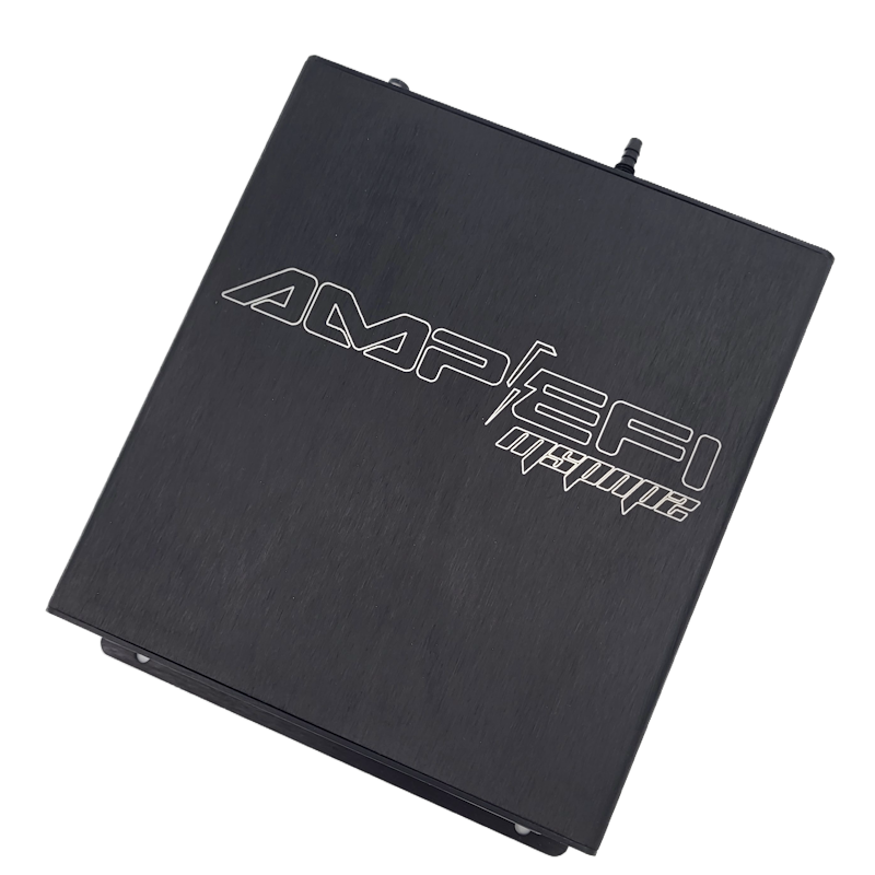
MSPNP2 EEC4B8 is a vehicle-specific MegaSquirt-II-based plug-in ECU. The manufacturer’s documentation lists 1994–1995 Mustang GT 5.0L. Confirm the ECU part number, engine, harness, region and transmission before use.
Application and version
The manufacturer’s index marks this MSPNP2 variant obsolete. This page describes the manufacturer’s version 2.0 documentation. Different hardware versions, optional jumpers and configurations can change installation details.
Installation and pinouts
Refer to the EEC4B8 version 2.0 installation guide for its model-specific wiring diagrams, connector orientation, sensor configuration and setup instructions. Check the exact installed configuration; avoid applying the pinout of an MS3Pro PNP or another vehicle. The manufacturer’s manual index also links older version documents.
Select and verify the correct base tune, check timing as directed and tune the specific engine after installation.
Main 60-way connector — B8 V2.0
The manufacturer's B8 installation guide supplies the following pin-function table. A dash means the guide does not identify a function, not that the vehicle's cavity is necessarily empty. Check its connector face and jumper settings for the exact unit.
| Pin | ECU function | Usage / note |
|---|---|---|
| 1 | 12 V battery | Constant supply |
| 2 | — | — |
| 3 | — | — |
| 4 | — | — |
| 5 | 12 V ignition | Ignition switch |
| 6 | Power ground | Ground |
| 7 | CLT | Coolant temperature sensor |
| 8 | — | — |
| 9 | — | — |
| 10 | A/C status | A/C idle up; see JP2 |
| 11 | — | — |
| 12 | INJB | Injector 6 |
| 13 | INJB | Injector 7 |
| 14 | INJB | Injector 8 |
| 15 | INJB | Injector 5 |
| 16 | Power ground | ICM ground |
| 17 | CEL | Check engine lamp |
| 18 | — | — |
| 19 | — | — |
| 20 | Power ground | Ground |
| 21 | IAC | Idle valve |
| 22 | Fuel pump | Fuel pump relay |
| 23 | — | — |
| 24 | — | — |
| 25 | IAT | Intake air temperature sensor |
| 26 | 5 V reference | Sensor supply |
| 27 | — | — |
| 28 | — | — |
| 29 | — | — |
| 30 | Clutch switch | Launch control |
| 31 | — | — |
| 32 | Output 2 | High fan |
| 33 | — | — |
| 34 | — | — |
| 35 | INJA | Injector 4 |
| 36 | SPOUT | SPOUT signal to ignition driver |
| 37 | 12 V ignition | Ignition switch |
| 38 | — | — |
| 39 | INJA | Injector 3 |
| 40 | Power ground | Ground |
| 41 | — | — |
| 42 | O2 sensor, right | See jumper J5 |
| 43 | O2 sensor, left | See jumper J5 |
| 44 | — | — |
| 45 | External MAP | Optional external MAP sensor; see JP4 |
| 46 | Sensor ground | Sensor return |
| 47 | TPS | Throttle position sensor |
| 48 | — | — |
| 49 | Power ground | Ground |
| 50 | — | — |
| 51 | — | — |
| 52 | — | — |
| 53 | — | — |
| 54 | — | — |
| 55 | Output 1 | Low fan |
| 56 | PIP | PIP signal from ignition driver |
| 57 | 12 V ignition | Ignition switch |
| 58 | INJA | Injector 1 |
| 59 | INJA | Injector 2 |
| 60 | Power ground | Ground |
Rear 26-way options connector — B8 V2.0
| Pin | Function | Manufacturer note |
|---|---|---|
| A | Analogue sensor ground | Sensor return |
| B | Power ground | |
| C | EGO | J5 jumper must be removed |
| D | Knock (ADC2) | |
| E | IAT | Duplicated on main connector pin 25 |
| F | External MAP sensor | JP4 to EXT; default internal MAP |
| G | CAN low | |
| H | 5 V DC output | |
| I | CAN high | |
| J | 12 V supply output | Fused at 500 mA |
| K | Table switch input | |
| L | VRIN2+ | Optional cam sensor input |
| M | Launch input | |
| N | Clutch input | Connects to launch input via JP16 |
| O | Tachometer output | |
| P | Output 2 | Duplicated on main connector pin 32 |
| Q | Output 1 | Duplicated on main connector pin 55 |
| R | Boost | |
| S | Ignition D | Optional wasted spark: cylinders 2 and 8 |
| T | Injector B | High impedance only |
| U | Ignition C | Optional wasted spark: cylinders 4 and 7 |
| V | Injector A | High impedance only |
| W | Ignition B | Optional wasted spark: cylinders 3 and 5 |
| X | Injector B | High impedance only |
| Y | Ignition A | Optional wasted spark: cylinders 1 and 6 |
| Z | Injector A | High impedance only |