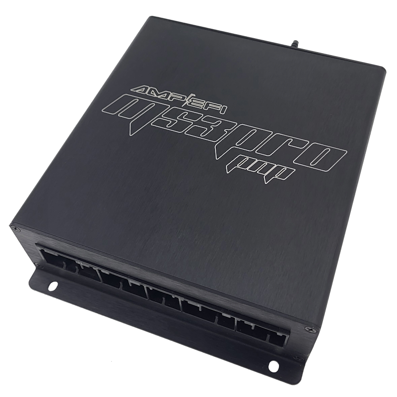
MSPNP-Pro EEC4A8 is a vehicle-specific MS3Pro-based plug-in engine management ECU. The manufacturer’s model-specific installation guide lists the following application: 1987–1993 Ford Mustang 5.0L and 1986–1988 Thunderbird 5.0L. Fitment depends on the original ECU connector, engine, harness and market; confirm the exact part number before installation.
Application and installation
A separate supplier overview includes 1986 Mustangs; the model-specific guide lists 1987–1993. Check the original ECU and harness with the supplier for a 1986 Mustang. Plug-in does not mean every optional feature is prewired: follow the relevant guide for setup, sensors, jumpers, base tune and ignition-timing checks.
Pinout and documentation
AMP EFI EEC4A8 vehicle-specific installation and connector documentation is the primary source for this model. Check the connector orientation, version and any configurable or optional functions before wiring. Diagrams may be shown as images in the guide; this page does not substitute a pin assignment from another MSPNP model.
See the manufacturer’s ECU documentation index and firmware and base-tune index. Initial maps require verification and tuning for the particular engine.
Rear options connector — A–Z
Transcribed from this application's AMP EFI installation guide. These are the rear options connections; they are not the complete factory vehicle connector pinout. Verify orientation, exact ECU variant, electrical limits and software configuration before wiring.
| Pin | Function | Default or note in source |
|---|---|---|
| A | Sensor ground | Sensor return |
| B | 5 V Vref out | Fused at 500 mA |
| C | External MAP sensor | Internal MAP default; move JP4 to EXT MAP |
| D | AIN2 | Spare analog input |
| E | EGO | Optional wideband O2 sensor |
| F | AIN1 | Spare analog input |
| G | VSS+ | Vehicle speed; duplicated on main connector pin 3 |
| H | CMP+ | Optional cam sensor input |
| I | DFIN2 | Digital frequency input 2 |
| J | Digital input 1 | Optional flex fuel |
| K | CANL | CAN low |
| L | High current output 1 | — |
| M | CANH | CAN high |
| N | Unused | Do not connect |
| O | Unused | Do not connect |
| P | High current output 3 | — |
| Q | Digital input 2 | — |
| R | Tach out | — |
| S | Ignition G | Optional spark cylinder 4 |
| T | Ignition H | Optional spark cylinder 8 |
| U | Ignition E | Optional spark cylinder 6 |
| V | Ignition F | Optional spark cylinder 5 |
| W | Ignition C | Optional spark cylinder 7 |
| X | Ignition D | Optional spark cylinder 2 |
| Y | Ignition A | Optional spark cylinder 1 |
| Z | Ignition B | Optional spark cylinder 3 |
60-way factory ECU connector
From the AMP EFI model-specific installation guide. A dash means the source does not give an assignment; it does not establish that the vehicle harness has no terminal. These EEC4A8 and EEC4B8 assignments differ; verify the actual ECU, orientation and jumper configuration.
| Pin | MS3 PNP function | Usage in guide |
|---|---|---|
| 1 | 12 V battery | Constant supply |
| 2 | — | — |
| 3 | VSS+ | DFIN1 |
| 4 | — | — |
| 5 | 12 V ignition | Ignition switch |
| 6 | VSS− | Ground |
| 7 | CLT | Coolant temperature sensor |
| 8 | — | — |
| 9 | — | — |
| 10 | A/C status | A/C idle up; see JP2 |
| 11 | — | — |
| 12 | INJB | Injector 3 |
| 13 | INJG | Injector 4 |
| 14 | INJF | Injector 5 |
| 15 | INJE | Injector 6 |
| 16 | Power ground | ICM ground |
| 17 | IAC2B | Check engine lamp |
| 18 | — | — |
| 19 | — | — |
| 20 | Power ground | Ground |
| 21 | IAC | Idle valve |
| 22 | Fuel pump | Fuel pump relay |
| 23 | Knock 1 | — |
| 24 | — | — |
| 25 | IAT | Intake air temperature sensor |
| 26 | 5 Vref | Sensor supply |
| 27 | — | — |
| 28 | — | — |
| 29 | O2 sensor, right | See jumper JP1 |
| 30 | Digital input 2 | Clutch switch |
| 31 | — | — |
| 32 | — | — |
| 33 | — | — |
| 34 | — | — |
| 35 | — | — |
| 36 | SPOUT | SPOUT signal to ignition driver |
| 37 | 12 V ignition | Ignition switch |
| 38 | — | — |
| 39 | — | — |
| 40 | Power ground | Ground |
| 41 | — | — |
| 42 | INJC | Injector 7 |
| 43 | O2 sensor, left | See jumper JP1 |
| 44 | — | — |
| 45 | External MAP | Optional external MAP sensor; see JP4 |
| 46 | Sensor ground | Sensor return |
| 47 | TPS | Throttle position sensor |
| 48 | — | — |
| 49 | Power ground | Ground |
| 50 | — | — |
| 51 | — | — |
| 52 | INJH | Injector 8 |
| 53 | — | — |
| 54 | PWM2 | A/C WOT cutout |
| 55 | — | — |
| 56 | PIP | PIP signal from ignition driver |
| 57 | 12 V ignition | Ignition switch |
| 58 | INJA | Injector 1 |
| 59 | INJD | Injector 2 |
| 60 | Power ground | Ground |