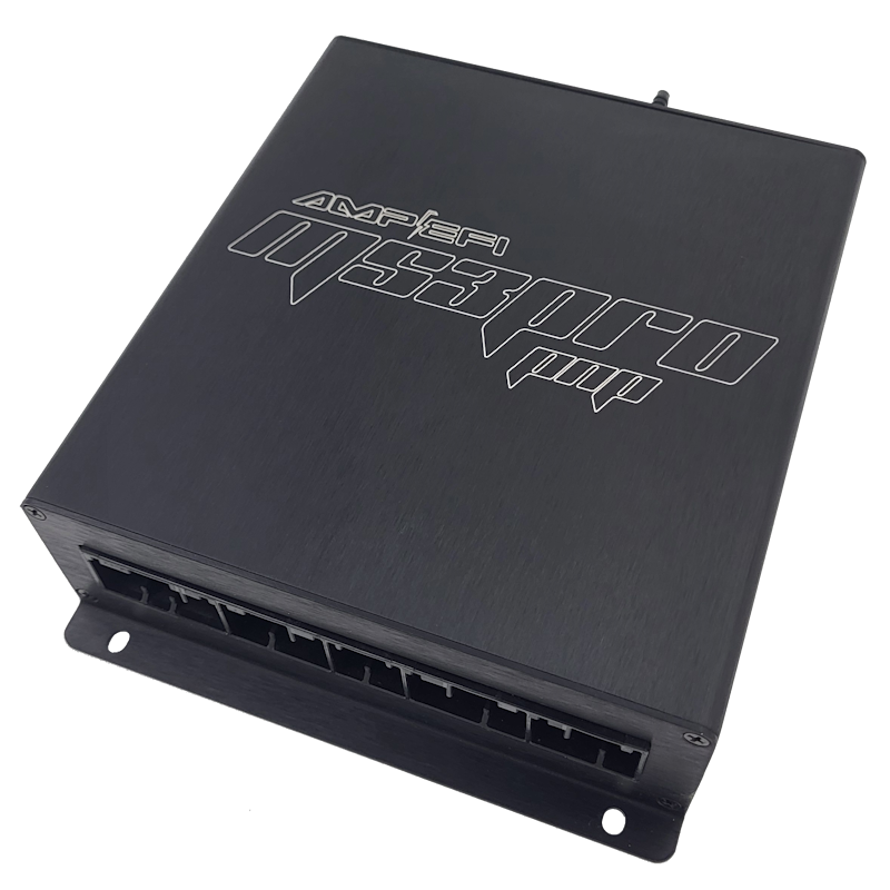
MSPNP-Pro E369699 is a vehicle-specific MS3Pro-based plug-in engine management ECU. The manufacturer’s model-specific installation guide lists the following application: 1996–1999 BMW E36 325i, 328i and M3 as listed in the manufacturer’s guide. Fitment depends on the original ECU connector, engine, harness and market; confirm the exact part number before installation.
Application and installation
The manufacturer shows rear option connector configurations for V1 and V2; verify the physical unit. Plug-in does not mean every optional feature is prewired: follow the relevant guide for setup, sensors, jumpers, base tune and ignition-timing checks.
Pinout and documentation
AMP EFI E369699 vehicle-specific installation and connector documentation is the primary source for this model. Check the connector orientation, version and any configurable or optional functions before wiring. Diagrams may be shown as images in the guide; this page does not substitute a pin assignment from another MSPNP model.
See the manufacturer’s ECU documentation index and firmware and base-tune index. Initial maps require verification and tuning for the particular engine.
Rear options connectors by hardware version
These tables follow the AMP EFI application guide. The guide labels the 26- and 22-position tables V2 and separately illustrates a 20-position options connector. Identify the installed ECU and connector generation before wiring; these are rear options, not the complete original BMW main connector.
V2 connector 1 — 26 positions
| Pin | Function | Default or notes |
|---|---|---|
| 1A | Spark out A | Coil A, cylinder 1; logic-level smart coil |
| 1B | Spark out B | Coil B, cylinder 5; logic-level smart coil |
| 1C | Spark out C | Coil C, cylinder 3; logic-level smart coil |
| 1D | Spark out D | Coil D, cylinder 6; logic-level smart coil |
| 1E | Spark out E | Coil E, cylinder 2; logic-level smart coil |
| 1F | Spark out F | Coil F, cylinder 4; logic-level smart coil |
| 1G | Injector out G | TPS signal transmit to factory traction control |
| 1H | Injector out H | — |
| 1I | Digital in 2 | — |
| 1J | Digital in 3 | — |
| 1K | Digital in 12 V | — |
| 1L | IAT | Aftermarket IAT; disconnect OE IAT if used |
| 1M | Digital frequency in 1 | Vehicle speed from ABS, 10k 5 V pull-up |
| 1N | Digital frequency in 2 | Available speed input |
| 1O | Analog in 1 | Assigned MAF; disconnect MAF to repurpose |
| 1P | Analog in 2 | General-purpose analog input |
| 1Q | Analog in 3 | General-purpose analog input |
| 1R | Analog in 4 | General-purpose analog input |
| 1S | Analog in 5 | General-purpose analog input |
| 1T | Analog in 6 | General-purpose analog input |
| 1U | Analog in 7 | General-purpose analog input |
| 1V | Analog in 8 / EGO | Wideband sensor input; can repurpose |
| 1W | CAN H | 120 ohm termination onboard |
| 1X | CAN L | 120 ohm termination onboard |
| 1Y | 5 V VREF out | Sensor 5 V power, internally fused 0.25 A |
| 1Z | Sensor ground | — |
V2 connector 2 — 22 positions
| Pin | Function | Default or notes |
|---|---|---|
| 2A | 12 V+ out | Ignition-switched; 0.25 A fuse; relay control only, not supply power |
| 2B | Digital input 1 / FLEX | Available flex sensor input |
| 2C | IAC1A | — |
| 2D | IAC1B | — |
| 2E | IAC2A | — |
| 2F | IAC2B | — |
| 2G | Injector out I | Fuel rate output to factory dash econometer; 1k 5 V pull-up |
| 2H | Injector out J | — |
| 2I | Tach out | Factory dashboard tachometer |
| 2J | High current out 1 | — |
| 2K | High current out 2 | — |
| 2L | High current out 3 | — |
| 2M | PWM out 2 | Idle valve; IAC close |
| 2N | PWM out 3 | VANOS camshaft control |
| 2O | PWM out 4 | — |
| 2P | PWM out 5 | — |
| 2Q | Unused | — |
| 2R | Unused | — |
| 2S | Unused | — |
| 2T | Unused | — |
| 2U | Unused | — |
| 2V | Unused | — |
20-position options connector
| Pin | Function | Default or notes |
|---|---|---|
| 1 | High current 1 | — |
| 2 | High current 2 | — |
| 3 | High current 3 | A/C relay; duplicates main pin 74 |
| 4 | Injector G | TPS retransmission to DSC; duplicates main pin 45 |
| 5 | Injector H | CEL; duplicates main pin 20 |
| 6 | CMP+ | Hall only, internal pull-up to 5 V; enable jumper JP10 |
| 7 | Vref +5 V | — |
| 8 | External MAP | Enable jumper JP11 EXT |
| 9 | Analog input 1 | MAF |
| 10 | EGO | — |
| 11 | Digital input 4 | — |
| 12 | Digital input 2 | — |
| 13 | Digital input 1 | — |
| 14 | CANL | — |
| 15 | CANH | — |
| 16 | DFIN3 | Hall / logic |
| 17 | DFIN2 | Hall / logic |
| 18 | Analog input 2 | — |
| 19 | IAT | — |
| 20 | Sensor return | — |
The V2 source marks pins 1A–1F, 1W–1Z, 2A–2B and 2S–2V large and the remainder small. Check the original for views, electrical limits and jumper settings.
88-way vehicle main connector
The AMP EFI E369699 installation guide provides the main connector chart below. A dash reproduces a blank in the source and does not prove a terminal or vehicle circuit is absent. Functions of JP2–JP6 and several options depend on the configured jumpers; consult the manufacturer drawing and verify hardware revision.
| Pin | MS3 I/O function | Usage in source |
|---|---|---|
| 1 | Ignition E | Ignition coil cylinder 2 |
| 2 | Ignition F | Ignition coil cylinder 4 |
| 3 | Ignition D | Ignition coil cylinder 6 |
| 4 | PGround | Power ground |
| 5 | Injector E | Injector cylinder 2 |
| 6 | Injector A | Injector cylinder 1 |
| 7 | SGround | Sensor ground |
| 8 | Analog input 1 | MAF sensor |
| 9 | Injector I | Fuel rate output |
| 10 | CLT | Coolant temperature sensor |
| 11 | — | — |
| 12 | TPS | Throttle position sensor |
| 13 | — | — |
| 14 | IAT | Intake air temperature sensor |
| 15 | DFIN1 | VSS |
| 16 | Digital input 3 | A/C request |
| 17 | — | — |
| 18 | — | — |
| 19 | — | — |
| 20 | Injector H | CEL |
| 21 | PWM3 | VANOS |
| 22 | Injector C | Injector cylinder 3 |
| 23 | Injector D | Injector cylinder 6 |
| 24 | Injector F | Injector cylinder 4 |
| 25 | High current 1 | EGO heater bank 1 via JP2 |
| 26 | Constant +12 V | Battery |
| 27 | PWM2 | IAC close |
| 28 | PGround | Power ground |
| 29 | Ignition A | Ignition coil cylinder 1 |
| 30 | Ignition C | Ignition coil cylinder 3 |
| 31 | Ignition B | Ignition coil cylinder 5 |
| 32 | PGround | Power ground |
| 33 | Injector B | Injector cylinder 5 |
| 34 | PGround | Power ground |
| 35 | — | — |
| 36 | TachOut | Tachometer |
| 37 | — | — |
| 38 | PGround | Power ground |
| 39 | SGround | Sensor ground |
| 40 | SGround | Sensor ground |
| 41 | PGround | Power ground |
| 42 | SGround | Sensor ground |
| 43 | PGround | Power ground |
| 44 | Vref | Sensor +5 V supply |
| 45 | Injector G | TPS to ABS |
| 46 | — | — |
| 47 | — | — |
| 48 | Vref | Crank position sensor +5 V supply |
| 49 | — | Ignition switch |
| 50 | — | — |
| 51 | — | — |
| 52 | High current 3 | Exhaust flap via JP3 |
| 53 | PWM1 | IAC open |
| 54 | 12 V supply | Main relay contacts |
| 55 | High current 1 | EGO heater bank 1 via JP2 |
| 56 | PGround | Power ground |
| 57 | Knock1 | Knock sensor |
| 58 | SGround | Sensor ground |
| 59 | Knock2 | Knock sensor |
| 60 | — | — |
| 61 | High current 2 | EGO heater bank 2 via JP5 |
| 62 | — | — |
| 63 | SGround | Sensor ground |
| 64 | — | Cam sensor reference |
| 65 | — | Cam sensor sense |
| 66 | — | — |
| 67 | SGround | Sensor ground |
| 68 | — | — |
| 69 | Fuel pump | Fuel pump relay |
| 70 | SGround | Sensor ground |
| 71 | SGround | Sensor ground |
| 72 | SGround | Sensor ground |
| 73 | — | Main relay coil activation |
| 74 | Injector J | A/C relay |
| 75 | O2 | Bank 1 sensor 1 via JP4 pins 1/2 |
| 76 | O2 | Bank 1 sensor 2 via JP4 pins 3/4 |
| 77 | O2 | Bank 2 sensor 1 via JP4 pins 5/6 |
| 78 | O2 | Bank 2 sensor 2 via JP4 pins 7/8 |
| 79 | High current 2 | EGO heater bank 2 via JP5 |
| 80 | Pull down to PGnd | ABS cutoff |
| 81 | Pull down to PGnd | ABS ZWV |
| 82 | Pull down to PGnd | ABS EML |
| 83 | CKP+ | Crankshaft position sensor + |
| 84 | — | — |
| 85 | CANL | Via JP6 pins 1/2 |
| 86 | CANH | Via JP6 pins 3/4 |
| 87 | 12 V supply | Main relay contacts |
| 88 | — | — |