Connectors
The first-generation (GEN1) Motorsport Electronics ME221 and ME100 wire-in ECUs use two TE plugs with 28 pins in total: a 12-way plug (TE 175965-2, pins 1 to 12) and a 16-way plug (TE 175966-2, pins 13 to 28), with TE 175265-1 crimps. Each plug has two rows: pins 1–6 above 7–12, and 13–20 above 21–28. The manufacturer's drawing shows the ECU header, with numbers corresponding to the wire side (back) of the harness plugs.
Pin assignments
The 12-way plug carries the ME221 outputs: injectors 1 to 4 (pins 5, 4, 7 and 1), low-side outputs 1 to 3 (pins 6, 3 and 2), the 12 V tachometer output (8), wasted-spark coil outputs A/1 for cylinders 1 and 4 (10) and B/2 for cylinders 2 and 3 (12), and power grounds (9 and 11). The 16-way plug carries switched 12 V ignition power (13, 5 A fused), the 5 V reference (14), cam and crank sensor inputs (15/22 and 23/16; the negative inputs are left unconnected for Hall or optical sensors), high-speed digital input 2 (17), intake-air and coolant temperature (18 and 19, 2.7 kΩ pull-up), O2 sensor (20, 0–5 V narrow or wideband), knock (24/21), spare analogue 1 (25), MAP (26), TPS (27) and analogue/sensor ground (28). The manufacturer warns against resistor-less or low-resistance plugs and leads on the coil outputs.
On the ignition-only ME100, the manufacturer annotates several injector and low-side pins as other low-side channels (LS4 to LS7). The source labels both pins 4 and 6 "LS5 on ME100"; that inconsistency is unresolved, so confirm with the manufacturer before using those ME100 outputs. Assignments and loom colours are manufacturer documentation (graded confirmed). This pinout does not apply to the GEN2 90-way units (see GEN2 90-way connector pinout) or to vehicle-specific plug-in boards.
Diagram redrawn by Tuning Wiki from the Motorsport Electronics ME100/ME221 GEN1 wire-in pinout. See the ME221 and ME100 GEN1 hubs.
Sources
- Motorsport Electronics, ME100/ME221 GEN1 Wire-In Pinout, online manual (© 2019), header drawing, TE part numbers, pin table and loom colours. Manufacturer documentation. Accessed 19 November 2026.
Connector pinout
Motorsport Electronics ME221 GEN1 and ME100 GEN1 wire-in ECUs (two TE plugs, 12-way 175965-2 and 16-way 175966-2, crimps 175265-1). Functions and loom colours from the manufacturer GEN1 wire-in pinout; ME100 annotations refer to the ignition-only ME100. Not applicable to GEN2 90-way units or plug-in boards.
View orientation is stated beside each photograph. Unknown functions remain in the pin index.
12-way plug (TE 175965-2)
View: ECU header as drawn by the manufacturer; numbers correspond to the wire side of the harness plugs
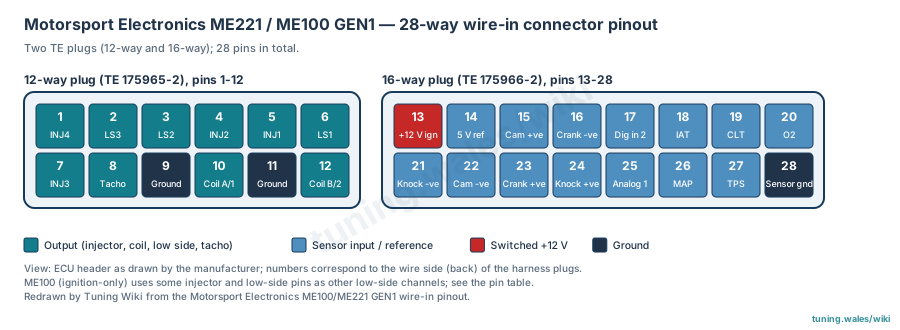
Select a pin in a photograph or the index to highlight it.
| Pin | Function / cavity | Confidence / source | Notes |
|---|---|---|---|
| Injector 4 Cavity: Populated |
Confirmed ME GEN1 wire-in pinout (online manual) |
Loom colour GREEN/ORANGE. | |
| Low Side Output 3 (LS7 on ME100) Cavity: Populated |
Confirmed ME GEN1 wire-in pinout (online manual) |
Loom colour BLUE/RED. | |
| Low Side Output 2 (LS6 on ME100) Cavity: Populated |
Confirmed ME GEN1 wire-in pinout (online manual) |
Loom colour BLUE/BROWN. | |
| Injector 2 (LS5 on ME100) Cavity: Populated |
Confirmed ME GEN1 wire-in pinout (online manual) |
Loom colour GREEN/BROWN. The source labels both pins 4 and 6 "LS5 on ME100"; this inconsistency is unresolved. | |
| Injector 1 (LS4 on ME100) Cavity: Populated |
Confirmed ME GEN1 wire-in pinout (online manual) |
Loom colour GREEN/BLACK. | |
| Low Side Output 1 (LS5 on ME100) Cavity: Populated |
Confirmed ME GEN1 wire-in pinout (online manual) |
Loom colour BLUE/BLACK. The source labels both pins 4 and 6 "LS5 on ME100"; this inconsistency is unresolved. | |
| Injector 3 (LS6 on ME100) Cavity: Populated |
Confirmed ME GEN1 wire-in pinout (online manual) |
Loom colour GREEN/RED. | |
| Tachometer Output (12V) Cavity: Populated |
Confirmed ME GEN1 wire-in pinout (online manual) |
Loom colour BROWN. | |
| GROUND Cavity: Populated |
Confirmed ME GEN1 wire-in pinout (online manual) |
Loom colour BLACK. | |
| Coil A / 1 (Cylinders 1 & 4) Cavity: Populated |
Confirmed ME GEN1 wire-in pinout (online manual) |
Loom colour BLUE. Do not use resistor-less or low-resistance plugs or leads (manufacturer warning). | |
| GROUND Cavity: Populated |
Confirmed ME GEN1 wire-in pinout (online manual) |
Loom colour BLACK. | |
| Coil B / 2(Cylinders 2 & 3) Cavity: Populated |
Confirmed ME GEN1 wire-in pinout (online manual) |
Loom colour GREEN. Do not use resistor-less or low-resistance plugs or leads (manufacturer warning). |
16-way plug (TE 175966-2)
View: ECU header as drawn by the manufacturer; numbers correspond to the wire side of the harness plugs
Select a pin in a photograph or the index to highlight it.
| Pin | Function / cavity | Confidence / source | Notes |
|---|---|---|---|
| 12V Ignition Switched Power (5A Fused) Cavity: Populated |
Confirmed ME GEN1 wire-in pinout (online manual) |
Loom colour RED. | |
| 5V Reference Output Cavity: Populated |
Confirmed ME GEN1 wire-in pinout (online manual) |
Loom colour PURPLE. | |
| CAM Sensor +ve Cavity: Populated |
Confirmed ME GEN1 wire-in pinout (online manual) |
Loom colour WHITE in SHIELDED RED. | |
| CRANK Sensor -ve (leave unconnected for hall/opto) Cavity: Populated |
Confirmed ME GEN1 wire-in pinout (online manual) |
Loom colour BLUE in SHIELDED BLACK. | |
| HS_Digital_Input_2 Cavity: Populated |
Confirmed ME GEN1 wire-in pinout (online manual) |
Loom colour RED/WHITE. | |
| Intake Air Temperature Signal (Pulled up via 2K7 Ohms) Cavity: Populated |
Confirmed ME GEN1 wire-in pinout (online manual) |
Loom colour ORANGE. | |
| Coolant Temperature Signal (Pulled up via 2K7 Ohms) Cavity: Populated |
Confirmed ME GEN1 wire-in pinout (online manual) |
Loom colour YELLOW. | |
| O2 Sensor Signal (0-5v, Narrow or Wideband) Cavity: Populated |
Confirmed ME GEN1 wire-in pinout (online manual) |
Loom colour RED/BLACK. | |
| Knock -ve Cavity: Populated |
Confirmed ME GEN1 wire-in pinout (online manual) |
Loom colour BLUE. | |
| CAM Sensor -ve (leave unconnected for hall/opto) Cavity: Populated |
Confirmed ME GEN1 wire-in pinout (online manual) |
Loom colour BLUE in SHIELDED RED. | |
| CRANK Sensor +ve Cavity: Populated |
Confirmed ME GEN1 wire-in pinout (online manual) |
Loom colour WHITE in SHIELDED BLACK. | |
| Knock +ve Cavity: Populated |
Confirmed ME GEN1 wire-in pinout (online manual) |
Loom colour White. | |
| Spare Analog 1 (0-5v) Cavity: Populated |
Confirmed ME GEN1 wire-in pinout (online manual) |
Loom colour RED/BLUE. | |
| MAP Sensor Signal Cavity: Populated |
Confirmed ME GEN1 wire-in pinout (online manual) |
Loom colour GREY. | |
| TPS Sensor Signal Cavity: Populated |
Confirmed ME GEN1 wire-in pinout (online manual) |
Loom colour PINK. | |
| Analog/Sensor Ground Cavity: Populated |
Confirmed ME GEN1 wire-in pinout (online manual) |
Loom colour BLACK. |