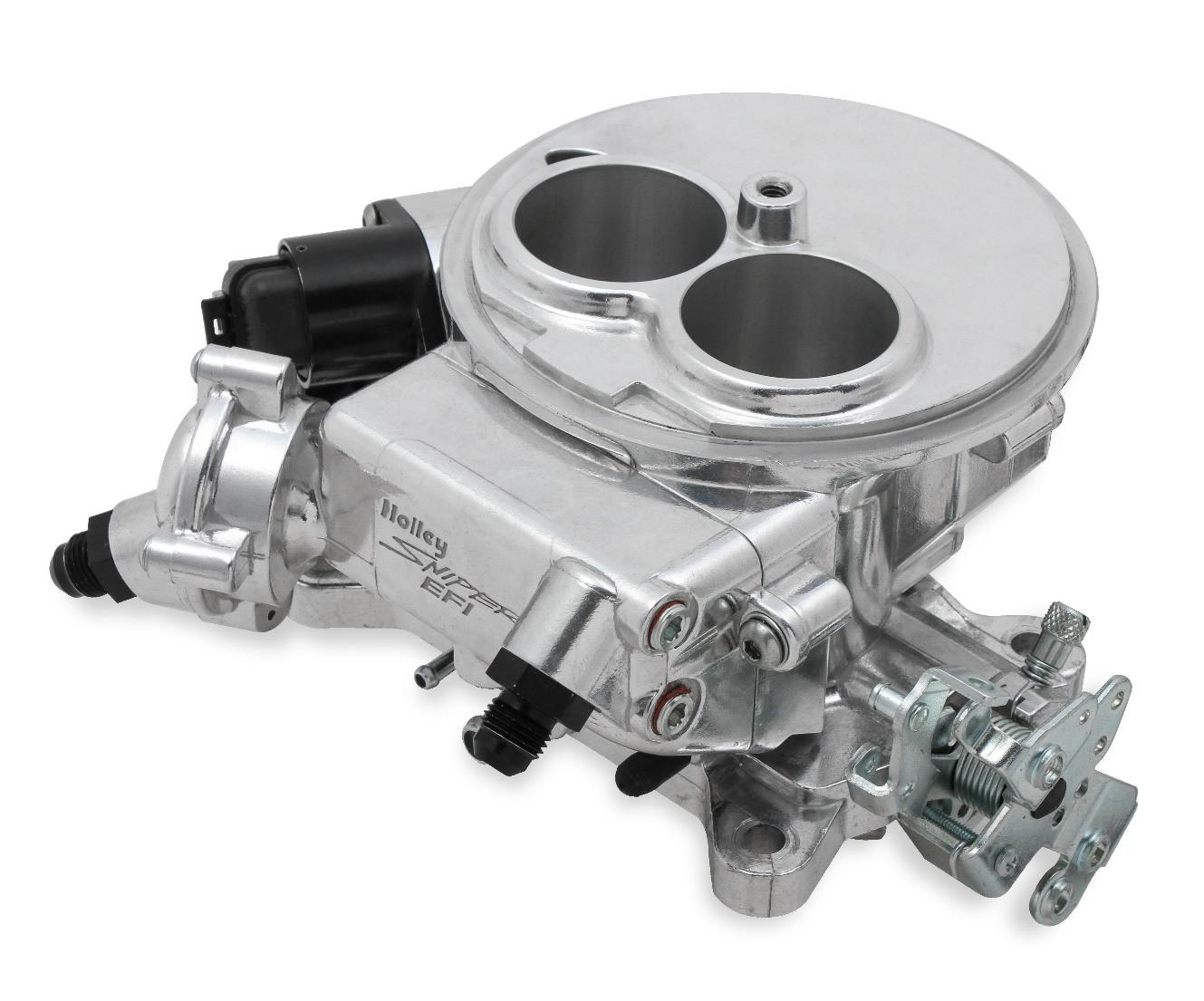
Holley Sniper EFI 2300 is a carburettor-replacement throttle-body fuel-injection system with integrated electronic control. The handheld is a setup/display device, and the system also requires appropriate fuel delivery, wiring and sensors.
Applications and versions
Designed for a Holley 2300-style two-barrel intake mounting flange. The two-injector system is listed for up to 350 hp naturally aspirated.
Two injectors; integrated ECU and fuel-pressure regulator. The 550-849, 550-850 and 550-851 identify finish variants; K-suffix master kits can include fuel-delivery parts. Model numbers: 550-849 / 550-850 / 550-851. See Holley’s Sniper model comparison.
Source discrepancy: Holley’s online comparison lists a boosted power figure for the two-injector 2300, while its 2300 quick-start says supercharged and turbocharged installations must use the four-injector Super Sniper. Confirm the application and exact kit with Holley. Holley 2300 quick-start.
Manufacturer harness connections
The model-specific Holley installation manual, PDF page 18, identifies the seven-way 558-490 main harness and ten-way 558-491 I/O harness below. The ten-way table has eight populated wires; the source does not assign the remaining two cavities. Outputs are relay-control signals: use the source for ratings, ignition configuration and the connector view. The throttle body, 4-pin CAN handheld connection, coolant sensor and oxygen sensor are separate connections.
Seven-way main harness, 558-490
| Pin | Wire colour | Manufacturer function |
|---|---|---|
| A | Violet | Crank signal positive |
| B | Dark green | Crank signal negative |
| C | Blue | Fuel-pump supply from relay |
| D | Yellow | Coil-negative engine-speed input |
| E | Red | Battery positive |
| F | Pink | Switched ignition +12 V |
| G | Black | Battery negative |
Ten-way I/O harness, 558-491
| Pin | Wire colour | Manufacturer function |
|---|---|---|
| A | Orange | Input 1, ground-triggered A/C |
| B | Yellow | Input 2, programmable ground input |
| C | Light blue | Output 1, fan 1 relay trigger |
| D | Light green | Output 2, fan 2 relay trigger |
| E | Grey | Output 6, A/C shutdown relay trigger |
| F | White | Points output for compatible ignition |
| G | Dark brown | Tachometer output |
| H | Tan | Digital gauge output |
Installation and ignition
The correct fuel pump, filters, sensor placement and ignition setup depend on the kit and vehicle. An RPM input alone does not establish ECU timing control; consult the manual and identify the ignition hardware before wiring.