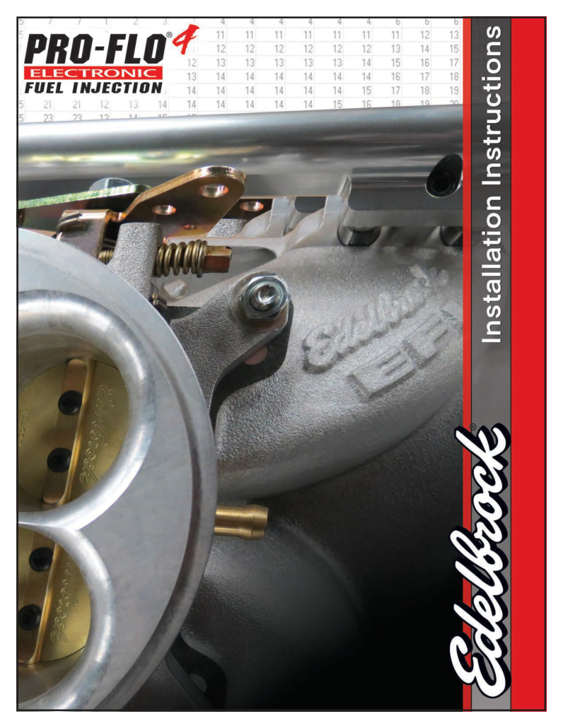
Edelbrock Pro-Flo 4 XT 35813 Small-Block Chevrolet: Edelbrock identifies 35813 as a Pro-Flo 4 XT kit for 1986 and earlier small-block Chevrolet engines. It uses a black XT intake manifold, individual port injectors, fuel rails, 90 mm throttle body and a separate ECU. The kit includes a compatible distributor for sequential control. Check engine and cylinder-head fitment before selecting the intake; this is not simply a carburettor-flange throttle-body swap.
Selection and system layout
Identify the exact ECU, engine and kit part number, intake and throttle, sensor and ignition arrangement. The phone or tablet app is the calibration and monitoring interface, not the ECU. Fuel delivery, return plumbing and auxiliary components depend on the package. Consult the manufacturer documentation for the specific configuration.
Wiring documentation
Use the model-specific Edelbrock source for hardware and wiring. The documented 37-1630 harness and 37-1631 branch connector references are given below; verify the harness part number and revision before applying them.
Pro-Flo 4 37-1630 main harness: ECU connector
Edelbrock’s 35813 instructions identify the main harness as 37-1630. The following 48-position schedule is transcribed from the 37-1630 drawing in Edelbrock’s Pro-Flo 4 instructions, printed page 17 (PDF page 19). Confirm the actual harness and revision; this is not the EZ-Street 30700 schedule. N/C is the manufacturer’s notation in this drawing, not proof of an unused position on other harnesses. The schematic does not explicitly state the connector viewing direction. The 35730 drawing labels both F4 CAN 1H and G4 CAN 1L as white; confirm the conductor identification against the actual harness and Edelbrock before connection.
| ECU position | Drawing signal | Illustrated wire |
|---|---|---|
| A1 | INJ 1 | LT BLUE |
| A2 | TACH OUT | BRWN/WHT |
| A3 | N/C | — |
| A4 | N/C | — |
| B1 | INJ 4 | BROWN |
| B2 | HT-LMB | BLK/BLU |
| B3 | APE | BLU/YEL |
| B4 | DIG GND | BLK/YLW |
| C1 | INJ 3 | PINK |
| C2 | IGN SW | PINK/BLK |
| C3 | IPN | BLUE/WHT |
| C4 | AIR T | YEL/BRWN |
| D1 | INJ 2 | GREEN |
| D2 | FAN 1 RELAY | BRWN/YLW |
| D3 | RT | BLU/ORG |
| D4 | ANA GND | BLK/WHT |
| E1 | IAC STEP C | GRN/WHT |
| E2 | IAC STEP B | GRN/YEL |
| E3 | RE + | BLU/RED |
| E4 | ANA GND | BLK/WHT |
| F1 | IAC STEP D | GRN/ORG |
| F2 | IAC STEP A | GRN/RED |
| F3 | COOL T | YEL/BLK |
| F4 | CAN 1H | WHITE |
| G1 | INJ 5 | DARK BLUE |
| G2 | FAN 2 RELAY | BRWN/ORG |
| G3 | TPS | GRN/BLU |
| G4 | CAN 1L | WHITE |
| H1 | INJ 8 | TAN |
| H2 | CRANK | YEL/ORG |
| H3 | MAP | GRN/WHT |
| H4 | VREF 1 | GREY |
| J1 | INJ 7 | YELLOW |
| J2 | CAM | YEL/VIOLET |
| J3 | FUEL PRESSURE | YEL/RED |
| J4 | MAIN RELAY | ORG/WHT |
| K1 | INJ 6 | VIOLET |
| K2 | N/C | — |
| K3 | N/C | — |
| K4 | N/C | — |
| L1 | OUT FUEL PUMP | TAN/WHT |
| L2 | VBATT IN | ORG |
| L3 | GND POW | BLK |
| L4 | GND POW | BLK |
| M1 | IGN 1 | WHT/VLT |
| M2 | IGN 2 | WHT/BLU |
| M3 | IGN 3 | WHT/GRN |
| M4 | IGN 4 | WHT/RED |
37-1631 injector/sensor harness branch connector
The 35813 instructions, printed page 22 (PDF page 24), show this separate 37-1631 sensor/injector harness connector. The 35813 kit documentation identifies the same harness part number. The lettered branch connector is not the ECU connector above.
| Branch position | Drawing signal | Illustrated wire |
|---|---|---|
| A | MAP | GRN/WHT |
| B | VREF | GREY |
| C | ANA GND | BLK/WHT |
| D | TPS | GRN/BLUE |
| E | FUEL PRESSURE | YEL/RED |
| F | AIR T | YEL/BRWN |
| G | COOL T | YEL/BLK |
| H | BATT POS | ORANGE |
| J | INJ 1 | LT BLUE |
| K | INJ 2 | GREEN |
| L | INJ 3 | PINK |
| M | INJ 4 | BROWN |
| N | INJ 5 | DARK BLUE |
| P | INJ 6 | VIOLET |
| R | INJ 7 | YELLOW |
| S | INJ 8 | TAN |