Edelbrock Pro-Flo 4 Plus 36130 GM Gen III/IV LS: Pro-Flo 4+ 36130 is the manufacturer’s engine-management kit listed for GM Gen III/IV LS. It uses a separate, weather-resistant ECU, a matching terminated harness and an application-specific base calibration; it controls an appropriate modern EFI engine and does not by itself replace a carburettor. Verify the engine generation, reluctor or trigger, sensors, throttle body, pedal, variable-cam and auxiliary harnesses against the exact kit. Edelbrock’s selection guide identifies this engine and kit number.
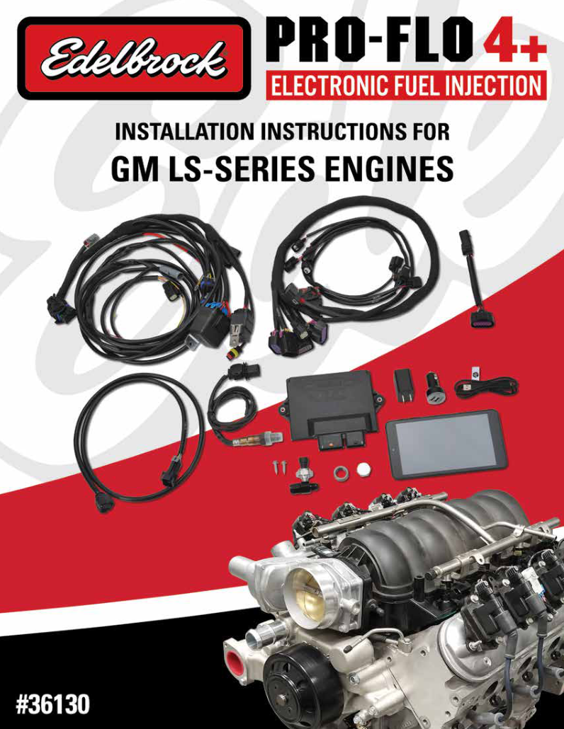
Selection and system layout
Identify the exact ECU, engine and kit part number, intake and throttle, sensor and ignition arrangement. The phone or tablet app is the calibration and monitoring interface, not the ECU. Fuel delivery, return plumbing and auxiliary components depend on the package. Consult the manufacturer documentation for the specific configuration.
Wiring documentation
Use the model-specific Edelbrock source for hardware and wiring. A complete numbered ECU connector table has not yet been verified for this page; do not substitute the assignment of another Pro-Flo or E-Street system.
Manufacturer harness connector references
Edelbrock’s kit 36130 installation manual, PDF pages 20–21, depicts main engine harness 37-1024 and chassis harness 37-1026. These tables identify the labelled branches and customer-wired leads, not the individual cavities of the ECU connectors. Confirm the actual kit, engine-specific extensions and connector orientation before wiring.
Main engine harness 37-1024
| Harness label | Manufacturer identification |
|---|---|
| ECU | Engine harness connector to the ECU; exact ECU cavity numbering is not supplied |
| BRIDGE | Connection to chassis harness bridge |
| INJ. R1–R4 | Four right-bank injector branches, individually labelled R1, R2, R3 and R4 |
| INJ. L1–L4 | Four left-bank injector branches, individually labelled L1, L2, L3 and L4 |
| KNOCK SENSOR | Connection to the applicable knock sensor harness |
| THROTTLE | Connection to the application throttle harness |
| IGNITION | Connection to the application ignition/coil harness |
| ENGINE POSITION | Connection to the application engine-position harness |
| SENS/OUT | Connection to the application sensors/outputs harness |
Chassis harness 37-1026
| Harness label | Manufacturer identification |
|---|---|
| ECU | Chassis harness ECU connection |
| BRIDGE | Connection to main engine harness bridge |
| CAN | CAN communication connector |
| APP | Accelerator pedal harness connection |
| O2 #1 | Primary oxygen sensor; manufacturer specifies this sensor |
| O2 #2 | Optional second oxygen sensor |
| FUEL PUMP | Grey two-way connector; source specifies maximum 10 A, with relay if the pump exceeds this |
| FANS | Low-current ground outputs to fan relay triggers, not direct fan power |
| MAIN RELAY / FUSE BOX | Power distribution and protection |
| Battery positive / negative | Battery connections; follow the manufacturer’s power and grounding instructions |
Chassis flying leads
| Wire colour | Function | Manufacturer notes |
|---|---|---|
| Pink/black | Ignition switch +12 V | Supply present in both ON and CRANK per manufacturer |
| Yellow/blue | Brake light switch | Brake input senses +12 V with brake pressed; part of drive-by-wire safety |
| Light blue/pink | Tachometer output | 12 V square-wave output according to the manual |
CAN harness connector — documented positions
The manual identifies a Deutsch DT04-4P mating connector and lists the following CAN positions. It does not establish functions for positions 3 and 4 in that description or give an explicit viewing orientation; do not infer them.
| Connector position | Function |
|---|---|
| 1 | CAN high |
| 2 | CAN low |
| 3 | Not specified in cited pin description |
| 4 | Not specified in cited pin description |
Source inconsistency: section 2.2 calls the large ECU connector a chassis-harness connector, while section 3.1 separately calls the chassis-harness connector the smaller one. The drawings label the engine and chassis harnesses separately. Confirm the exact connector identification against the actual harness and Edelbrock before connecting.
Engine-specific harness selection
The LS manual lists 24X ignition/engine-position harness 36112 or 58X harness 36122, and single-throttle harness 36132 or dual-throttle harness 36142, separately. It also identifies sensor harness 36165 for a two-pin alternator or 36155 for a four-pin alternator. Confirm the crank trigger and optional parts against PDF pages 11–12. Kit manual.