Connector pinout
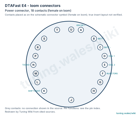
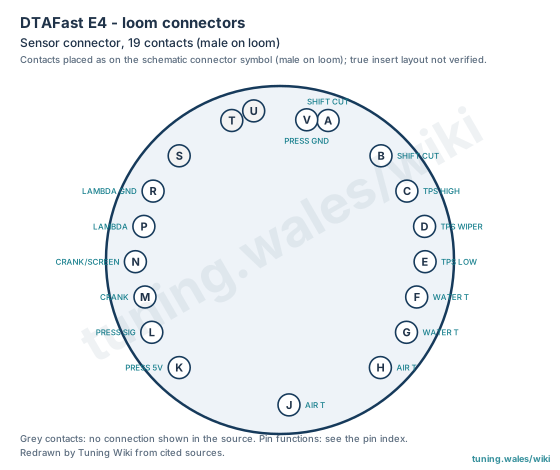
The historic DTAFast E4 four-cylinder ECU is wired through two circular loom connectors shown in the DTAFast wiring schematics dated 14 February 1997: an 18-contact power connector, female on the loom (contacts A to H, J to N and P to U), and a 19-contact sensor connector, male on the loom (contacts A to H, J to N and P to V). The sensor schematic is shared with the E6 and E8.
On the power connector, A is the ignition-switched supply, B and C are battery negative (both must be connected), D and E drive the earth sides of ignition coils 1 and 2, F is the injector output (drawn with four injectors fed from the ignition switch or relay), K is a gear-change light output rated at 20 W and N is the tachometer output. The other power contacts have no connection shown in this schematic.
On the sensor connector, A and B take the shift-cut switch, C, D and E the throttle potentiometer (C is the high side with the throttle open, D the wiper), F and G the water-temperature sensor, H and J the air-temperature sensor, K, L and V the 5 V supply, signal and earth of a pressure sensor (shown with Marelli sensor pin numbers), M and N the crank sensor, and P and R the lambda sensor. The schematic calls for screened crank-sensor cable with the screen on N, reversed polarity for Ford or Marelli crank sensors compared with the Vauxhall sensor shown, and R on the earthed side of the lambda sensor. S, T and U have no connection shown.
The drawings place the contacts as they appear around the schematic connector symbols; the true insert layout is not verified. Contacts with no connection shown are listed without a function, which does not establish that they are unused in every build.
Sources
- DTAFast, Four cylinder power wiring schematic, dated 14 February 1997. Manufacturer documentation. Accessed 19 November 2026.
- DTAFast, Sensor wiring schematic (E4/E6/E8), dated 14 February 1997. Manufacturer documentation. Accessed 19 November 2026.
Connector pinout
DTAFast E4 (historic four-cylinder ECU), from the DTAFast four-cylinder power wiring schematic and the E4/E6/E8 sensor wiring schematic, both dated 14 February 1997. Two circular loom connectors: an 18-contact power connector (female on the loom) and a 19-contact sensor connector (male on the loom). Contacts are drawn in the positions of the schematic connector symbols; the true insert layout is not verified. Contacts with no connection drawn in these schematics are listed without a function; that does not establish that they are unused in every build.
View orientation is stated beside each photograph. Unknown functions remain in the pin index.
Power connector, 18 contacts (female on loom)
View: Contacts placed as on the schematic connector symbol (female on loom); true insert layout not verified.
Select a pin in a photograph or the index to highlight it.
| Pin | Function / cavity | Confidence / source | Notes |
|---|---|---|---|
| Ignition-switched supply Cavity: Populated |
Confirmed DTAFast schematics 14/2/97 |
||
| Battery negative / ground Cavity: Populated |
Confirmed DTAFast schematics 14/2/97 |
Both battery-negative wires must be connected. | |
| Battery negative / ground Cavity: Populated |
Confirmed DTAFast schematics 14/2/97 |
Both battery-negative wires must be connected. | |
| Coil 1 (earth side) Cavity: Populated |
Confirmed DTAFast schematics 14/2/97 |
||
| Coil 2 (earth side) Cavity: Populated |
Confirmed DTAFast schematics 14/2/97 |
||
| Injectors (bank 1) Cavity: Populated |
Confirmed DTAFast schematics 14/2/97 |
The drawing shows four injectors on this output, fed from the ignition switch or relay. | |
| Unknown function Cavity: Unknown |
Unknown | ||
| Unknown function Cavity: Unknown |
Unknown | ||
| Unknown function Cavity: Unknown |
Unknown | ||
| Gear-change light output Cavity: Populated |
Confirmed DTAFast schematics 14/2/97 |
20 W maximum. | |
| Unknown function Cavity: Unknown |
Unknown | ||
| Unknown function Cavity: Unknown |
Unknown | ||
| Tachometer output Cavity: Populated |
Confirmed DTAFast schematics 14/2/97 |
||
| Unknown function Cavity: Unknown |
Unknown | ||
| Unknown function Cavity: Unknown |
Unknown | ||
| Unknown function Cavity: Unknown |
Unknown | ||
| Unknown function Cavity: Unknown |
Unknown | ||
| Unknown function Cavity: Unknown |
Unknown |
Sensor connector, 19 contacts (male on loom)
View: Contacts placed as on the schematic connector symbol (male on loom); true insert layout not verified.
Select a pin in a photograph or the index to highlight it.
| Pin | Function / cavity | Confidence / source | Notes |
|---|---|---|---|
| Shift-cut switch terminal 2 Cavity: Populated |
Confirmed DTAFast schematics 14/2/97 |
||
| Shift-cut switch terminal 1 Cavity: Populated |
Confirmed DTAFast schematics 14/2/97 |
||
| Throttle potentiometer, high side (throttle open) Cavity: Populated |
Confirmed DTAFast schematics 14/2/97 |
||
| Throttle potentiometer wiper Cavity: Populated |
Confirmed DTAFast schematics 14/2/97 |
||
| Throttle potentiometer, opposite end Cavity: Populated |
Confirmed DTAFast schematics 14/2/97 |
||
| Water temperature sensor terminal 1 Cavity: Populated |
Confirmed DTAFast schematics 14/2/97 |
||
| Water temperature sensor terminal 2 Cavity: Populated |
Confirmed DTAFast schematics 14/2/97 |
||
| Air temperature sensor terminal 1 Cavity: Populated |
Confirmed DTAFast schematics 14/2/97 |
||
| Air temperature sensor terminal 2 Cavity: Populated |
Confirmed DTAFast schematics 14/2/97 |
||
| Pressure sensor 5 V supply (pin 3 of the Marelli sensor) Cavity: Populated |
Confirmed DTAFast schematics 14/2/97 |
||
| Pressure sensor signal (pin 1 of the Marelli sensor) Cavity: Populated |
Confirmed DTAFast schematics 14/2/97 |
||
| Crank sensor terminal 1 Cavity: Populated |
Confirmed DTAFast schematics 14/2/97 |
Vauxhall sensor pin 1 to M; Ford/Marelli sensor polarity reversed. Screened cable. | |
| Crank sensor terminal 2 and screen Cavity: Populated |
Confirmed DTAFast schematics 14/2/97 |
Vauxhall sensor pin 2 and pin 3 (shield) to N. | |
| Lambda sensor terminal 2 Cavity: Populated |
Confirmed DTAFast schematics 14/2/97 |
||
| Lambda sensor earthed side Cavity: Populated |
Confirmed DTAFast schematics 14/2/97 |
Pin R must be connected to the earthed side of the lambda sensor. | |
| Unknown function Cavity: Unknown |
Unknown | ||
| Unknown function Cavity: Unknown |
Unknown | ||
| Unknown function Cavity: Unknown |
Unknown | ||
| Pressure sensor earth (pin 2 of the Marelli sensor) Cavity: Populated |
Confirmed DTAFast schematics 14/2/97 |