Connector pinout
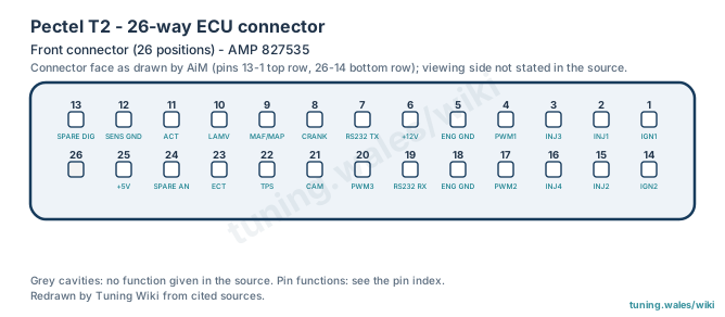
The Pectel T2 has a single 26-position front connector, identified as AMP 827535 in the AiM data-logger connection manual. The connector is drawn with two rows of 13 positions: pins 13 to 1 along the top row and 26 to 14 along the bottom row, numbered from right to left. Positions 1 to 25 are assigned; position 26 has no function in the source.
The pins carry the four high-impedance injector outputs (2, 15, 3, 16), the two ignition outputs (1 and 14, low-side or TTL coil drive as a build option), three low-side PWM outputs rated at 10 A (4, 17, 20), crank and cam inputs (8, 21), analogue inputs for MAF/MAP, TPS, coolant and air temperature and lambda, a spare analogue and a spare digital input, the 5 V sensor supply (25, 200 mA) and sensor ground (12). The ECU is powered through pin 6 (+12 V) with engine grounds on pins 5 and 18; the RS-232 link uses pin 7 (ECU transmit) and pin 19 (ECU receive).
The schedule comes from a data-logger vendor's manual rather than Pectel or Cosworth documentation, so the functions are graded as suspected. The viewing side of the drawing is not stated. Confirm the exact ECU build and its electrical limits before wiring.
Sources
- AiM, Technical documentation: communication and connection manual, ECU-AIM loggers, version 1.21, 21 March 2007, Pectel T2 section, p. 52. Data-logger vendor documentation. Accessed 19 November 2026.
Connector pinout
Pectel T2 (historic Pectel / Cosworth four-cylinder motorsport ECU). Pin schedule as published in the AiM data-logger connection manual v1.21 (2007), which shows a 26-position AMP 827535 connector with 25 assigned positions; position 26 has no function in the source. Third-party (data-logger vendor) documentation, not a Pectel/Cosworth document, so pin functions are graded suspected. Ignition output type is a build option.
View orientation is stated beside each photograph. Unknown functions remain in the pin index.
Front connector (26 positions)
Connector reference: AMP 827535
View: Connector face as drawn by AiM (pins 13-1 top row, 26-14 bottom row); viewing side not stated in the source.
Select a pin in a photograph or the index to highlight it.
| Pin | Function / cavity | Confidence / source | Notes |
|---|---|---|---|
| Ignition output 1 (IGN1) Cavity: Populated |
Suspected AiM ECU-AIM logger connection manual v1.21 (2007), p. 52 |
Build option: low-side or TTL coil driver. | |
| Injector 1 (high impedance) Cavity: Populated |
Suspected AiM ECU-AIM logger connection manual v1.21 (2007), p. 52 |
High-impedance injectors only. | |
| Injector 3 (high impedance) Cavity: Populated |
Suspected AiM ECU-AIM logger connection manual v1.21 (2007), p. 52 |
High-impedance injectors only. | |
| PWM output 1 (low side) Cavity: Populated |
Suspected AiM ECU-AIM logger connection manual v1.21 (2007), p. 52 |
10 A maximum. | |
| Engine ground Cavity: Populated |
Suspected AiM ECU-AIM logger connection manual v1.21 (2007), p. 52 |
||
| +12 V supply Cavity: Populated |
Suspected AiM ECU-AIM logger connection manual v1.21 (2007), p. 52 |
||
| RS-232 TX (ECU transmit) Cavity: Populated |
Suspected AiM ECU-AIM logger connection manual v1.21 (2007), p. 52 |
||
| Crank sensor input Cavity: Populated |
Suspected AiM ECU-AIM logger connection manual v1.21 (2007), p. 52 |
||
| MAF/MAP analogue input Cavity: Populated |
Suspected AiM ECU-AIM logger connection manual v1.21 (2007), p. 52 |
||
| Lambda sensor voltage (LAMV) Cavity: Populated |
Suspected AiM ECU-AIM logger connection manual v1.21 (2007), p. 52 |
||
| Air temperature (ACT) analogue input Cavity: Populated |
Suspected AiM ECU-AIM logger connection manual v1.21 (2007), p. 52 |
||
| Sensor ground (analogue ground) Cavity: Populated |
Suspected AiM ECU-AIM logger connection manual v1.21 (2007), p. 52 |
||
| Spare digital (switched) input Cavity: Populated |
Suspected AiM ECU-AIM logger connection manual v1.21 (2007), p. 52 |
||
| Ignition output 2 (IGN2) Cavity: Populated |
Suspected AiM ECU-AIM logger connection manual v1.21 (2007), p. 52 |
Build option: low-side or TTL coil driver. | |
| Injector 2 (high impedance) Cavity: Populated |
Suspected AiM ECU-AIM logger connection manual v1.21 (2007), p. 52 |
High-impedance injectors only. | |
| Injector 4 (high impedance) Cavity: Populated |
Suspected AiM ECU-AIM logger connection manual v1.21 (2007), p. 52 |
High-impedance injectors only. | |
| PWM output 2 (low side) Cavity: Populated |
Suspected AiM ECU-AIM logger connection manual v1.21 (2007), p. 52 |
10 A maximum. | |
| Engine ground Cavity: Populated |
Suspected AiM ECU-AIM logger connection manual v1.21 (2007), p. 52 |
||
| RS-232 RX (ECU receive) Cavity: Populated |
Suspected AiM ECU-AIM logger connection manual v1.21 (2007), p. 52 |
||
| PWM output 3 (low side) Cavity: Populated |
Suspected AiM ECU-AIM logger connection manual v1.21 (2007), p. 52 |
10 A maximum. | |
| Cam sensor input Cavity: Populated |
Suspected AiM ECU-AIM logger connection manual v1.21 (2007), p. 52 |
||
| Throttle position (TPS) analogue input Cavity: Populated |
Suspected AiM ECU-AIM logger connection manual v1.21 (2007), p. 52 |
||
| Coolant temperature (ECT) analogue input Cavity: Populated |
Suspected AiM ECU-AIM logger connection manual v1.21 (2007), p. 52 |
||
| Spare analogue input Cavity: Populated |
Suspected AiM ECU-AIM logger connection manual v1.21 (2007), p. 52 |
||
| +5 V sensor supply Cavity: Populated |
Suspected AiM ECU-AIM logger connection manual v1.21 (2007), p. 52 |
200 mA maximum. | |
| Unknown function Cavity: Unknown |
Unknown |