BossECU Opel C1XSE is an application-specific standalone ECU sold by BossGarage for the original engine wiring harness. The manufacturer’s product page describes it as a plug-and-play replacement; confirm the donor engine, original ECU family, connector and vehicle equipment before choosing it.
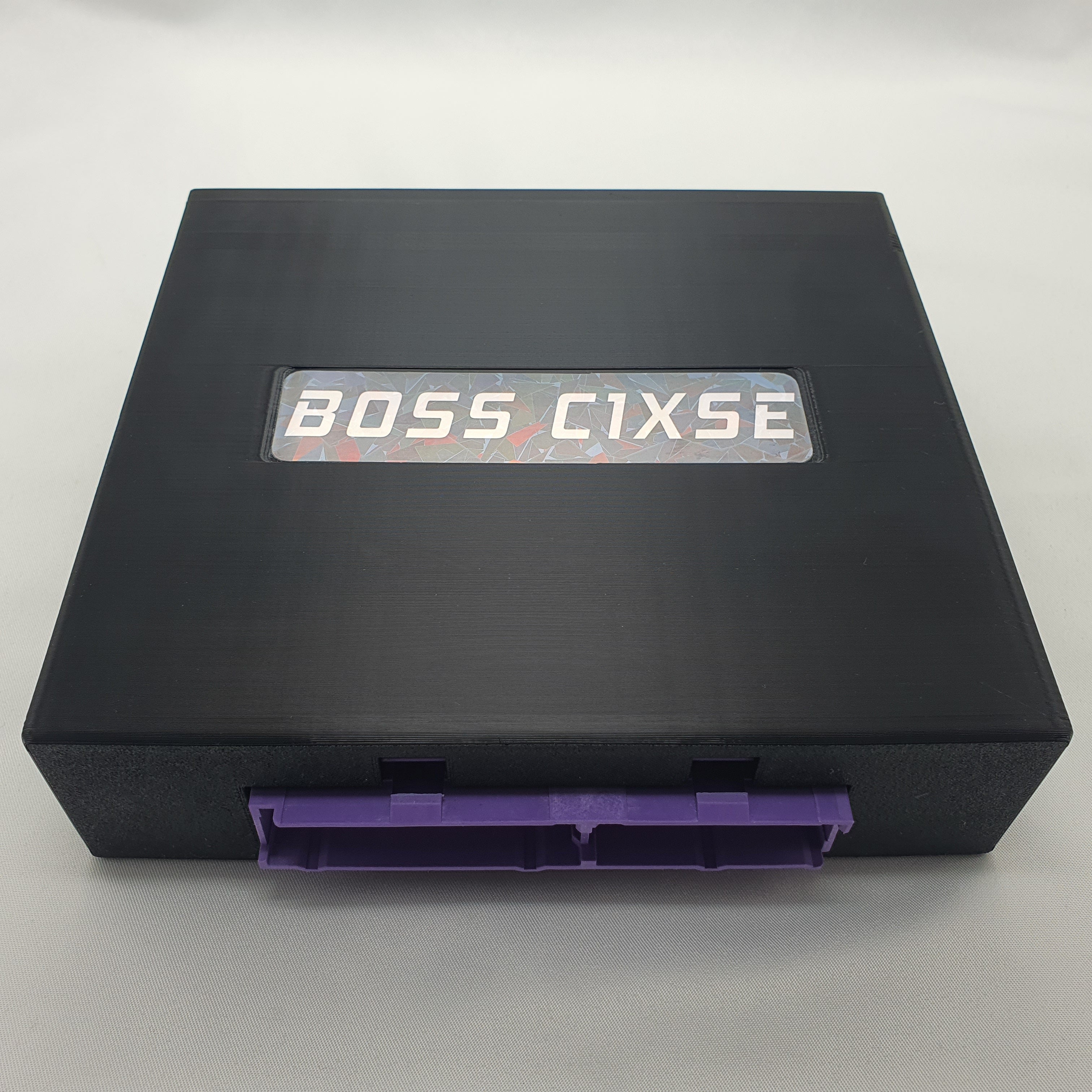
Manufacturer-listed applications
The combinations below are those named by BossGarage. Engine swaps, regional variants and changes to the original wiring can change compatibility. A vehicle model alone does not establish the original ECU or connector type.
| Engine / original ECU | Manufacturer-listed application |
|---|---|
| C14SE | Original C14SE engine wiring harness |
| C16SE | Original C16SE engine wiring harness |
Control and setup
BossGarage describes TunerStudio real-time tuning, VE-based fuel maps up to 32 × 32, an integrated controller for an LSU 4.9 wideband sensor, launch and boost control, and optional electronic-throttle hardware. It lists 14 analogue inputs and 24 low-side outputs on this product page; availability at the vehicle connector and the assignment of functions must be checked against the actual build and configuration. Wideband sensor, throttle hardware and other accessories may require additional components and wiring.
Connector and wiring
The manufacturer’s sales listing identifies the matching original harness but does not provide a complete cavity-by-cavity connector schedule. The manufacturer’s revision V1 guide lists a partial ECU-terminal schedule; see below. Complete cavity assignments and other board revisions remain unverified. Do not infer every signal assignment from another BossECU, a superficially similar connector or the factory ECU: obtain the exact model and hardware revision wiring information from BossGarage before wiring or testing.
Documentation
BossECU Opel C1XSE product and application information; BossGarage plug-and-play range. See the BossECU manufacturer index.
C1XSE V1 manufacturer ECU terminals — partial
BossGarage’s BossECU C1XSE V1 guide, section 18, labels the following ECU terminals and corresponding TunerStudio channel names. These are only the terminals the guide lists; omission does not establish an unused position. The TunerStudio pin labels are software channel names, not physical connector cavities. This V1 schedule must not be assumed to apply to later C1XSE boards.
Inputs
| ECU terminal | Documented function | TunerStudio pin label |
|---|---|---|
| A2 | VR1+ | Not listed |
| A7 | Manifold pressure | A3 |
| A8 | Throttle position | A2 |
| B3 | VR1− | Not listed |
| B12 | Coolant temperature | A1 |
| D3 | Intake temperature | A0 |
Outputs
| ECU terminal | Documented function | TunerStudio pin label |
|---|---|---|
| B6 | Fuel pump / injectors relay | D45 |
| C1 | CEL light | D23 |
| C3 | Ignition 2 | D38 |
| C10 | Injectors 1+2 | D8 |
| C11 | Injectors 3+4 | D9 |
| D10 | Ignition 1 | D40 |
The V1 guide also describes PCB pads for fan-relay control, clutch-switch input, boost output, tachometer and 0–5 V wideband-controller input; it does not assign factory connector numbers to those optional pads in this list. It specifies high-impedance injectors above 8 Ω or a resistor box for low-impedance injectors, and identifies an ignition-output voltage selection jumper; follow the exact guide and board marking.