The Autronic SM3 and its marine variant, the SM3MR, use a 42-way sealed main connector. The assignments below follow Autronic's standard loom drawing SM3_0001 (revision 1.1), checked against the numbered SM3 input/output function sheet dated 12 October 2016, both manufacturer documents. Autronic's wiring index states that the drawing also suits SM3 Marine.
Orientation and numbering
Autronic's drawing shows the connector from the wire side. The cited documents do not provide a cavity map that can be redrawn, so the diagram is a numbered pin index in a regular grid and does not represent cavity positions. An earlier transcription of this table had the numbers in the outer two connector rows reversed; the numbering here has been checked against the numbered function sheet.
Notable functions
The standard loom provides six saturated injector outputs (injector 6 shares pin 18 with switch input 1), four push-pull ignition outputs, eight general outputs (some doubling as stepper drivers or tachometer), two PWM outputs, three high-speed inputs and two analogue inputs, plus the cylinder and sync trigger pairs. The drawing specifies saturated injector drivers and calls for ballast with low-impedance injectors, with a minimum load of 5 ohms per output. Pin 15 is the main +12 V supply and pin 30 the separate +12 V RAM supply.
Diagram redrawn by Tuning Wiki from Autronic drawing SM3_0001 revision 1.1.
Not established
The SM3DC dual-calibration variant is not covered: Autronic's SM3 I/O sheet is labelled SM3 and does not state the calibration-switch wiring for SM3DC. Cavity layout is not shown.
Sources
- SM3 standard loom drawing SM3_0001 revision 1.1. Autronic manufacturer wiring drawing. Accessed 19 November 2026.
- SM3 input/output functions. Autronic manufacturer sheet, 12 October 2016. Accessed 19 November 2026.
- Autronic wiring diagram index. Manufacturer. Accessed 19 November 2026.
Connector pinout
Autronic SM3 standard loom drawing SM3_0001 revision 1.1 checked against the numbered SM3 input/output function sheet (12 October 2016); Autronic states the drawing also suits SM3 Marine. Manufacturer documentation. Not verified for SM3DC.
View orientation is stated beside each photograph. Unknown functions remain in the pin index.
Main connector (42-way)
View: Pin index only; physical cavity layout is not shown in the cited Autronic document.
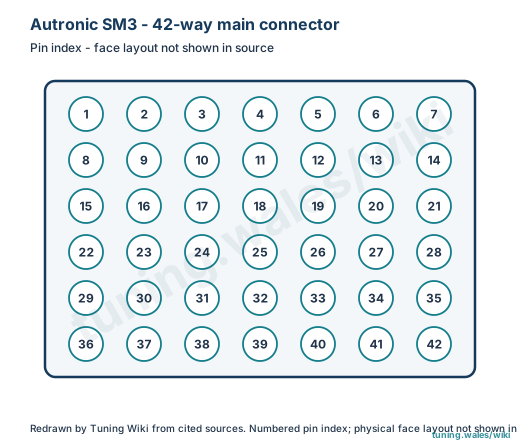
Select a pin in a photograph or the index to highlight it.
| Pin | Function / cavity | Confidence / source | Notes |
|---|---|---|---|
| Ignition switch input Cavity: Populated |
Confirmed Autronic SM3 loom drawing / I-O sheet |
||
| Switch input 3 Cavity: Populated |
Confirmed Autronic SM3 loom drawing / I-O sheet |
||
| Switch input 2 Cavity: Populated |
Confirmed Autronic SM3 loom drawing / I-O sheet |
||
| Injector output 5 Cavity: Populated |
Confirmed Autronic SM3 loom drawing / I-O sheet |
||
| Ignition output 1 Cavity: Populated |
Confirmed Autronic SM3 loom drawing / I-O sheet |
||
| Ignition output 2 Cavity: Populated |
Confirmed Autronic SM3 loom drawing / I-O sheet |
||
| Output 1 / stepper Cavity: Populated |
Confirmed Autronic SM3 loom drawing / I-O sheet |
||
| Analogue input 1 Cavity: Populated |
Confirmed Autronic SM3 loom drawing / I-O sheet |
||
| Coolant temperature input Cavity: Populated |
Confirmed Autronic SM3 loom drawing / I-O sheet |
||
| HSI input 1 Cavity: Populated |
Confirmed Autronic SM3 loom drawing / I-O sheet |
||
| +8 V trigger supply Cavity: Populated |
Confirmed Autronic SM3 loom drawing / I-O sheet |
||
| Output 8 / tachometer Cavity: Populated |
Confirmed Autronic SM3 loom drawing / I-O sheet |
||
| Output 6 Cavity: Populated |
Confirmed Autronic SM3 loom drawing / I-O sheet |
||
| PWM output 2 Cavity: Populated |
Confirmed Autronic SM3 loom drawing / I-O sheet |
||
| +12 V main supply Cavity: Populated |
Confirmed Autronic SM3 loom drawing / I-O sheet |
||
| Injector output 4 Cavity: Populated |
Confirmed Autronic SM3 loom drawing / I-O sheet |
||
| Injector output 1 Cavity: Populated |
Confirmed Autronic SM3 loom drawing / I-O sheet |
||
| Injector output 6 / switch input 1 Cavity: Populated |
Confirmed Autronic SM3 loom drawing / I-O sheet |
||
| Ignition output 3 Cavity: Populated |
Confirmed Autronic SM3 loom drawing / I-O sheet |
||
| Output 3 / stepper Cavity: Populated |
Confirmed Autronic SM3 loom drawing / I-O sheet |
||
| Throttle position input Cavity: Populated |
Confirmed Autronic SM3 loom drawing / I-O sheet |
||
| Sensor ground Cavity: Populated |
Confirmed Autronic SM3 loom drawing / I-O sheet |
||
| Intake air temperature input Cavity: Populated |
Confirmed Autronic SM3 loom drawing / I-O sheet |
||
| HSI input 2 Cavity: Populated |
Confirmed Autronic SM3 loom drawing / I-O sheet |
||
| Cylinder trigger positive Cavity: Populated |
Confirmed Autronic SM3 loom drawing / I-O sheet |
||
| Sync trigger positive Cavity: Populated |
Confirmed Autronic SM3 loom drawing / I-O sheet |
||
| Output 5 Cavity: Populated |
Confirmed Autronic SM3 loom drawing / I-O sheet |
||
| PWM output 1 Cavity: Populated |
Confirmed Autronic SM3 loom drawing / I-O sheet |
||
| Power supply ground Cavity: Populated |
Confirmed Autronic SM3 loom drawing / I-O sheet |
||
| +12 V RAM supply Cavity: Populated |
Confirmed Autronic SM3 loom drawing / I-O sheet |
||
| Injector output 3 Cavity: Populated |
Confirmed Autronic SM3 loom drawing / I-O sheet |
||
| Injector output 2 Cavity: Populated |
Confirmed Autronic SM3 loom drawing / I-O sheet |
||
| Ignition output 4 Cavity: Populated |
Confirmed Autronic SM3 loom drawing / I-O sheet |
||
| Output 2 / stepper Cavity: Populated |
Confirmed Autronic SM3 loom drawing / I-O sheet |
||
| Output 4 / stepper Cavity: Populated |
Confirmed Autronic SM3 loom drawing / I-O sheet |
||
| +5 V sensor supply Cavity: Populated |
Confirmed Autronic SM3 loom drawing / I-O sheet |
||
| Oxygen sensor input Cavity: Populated |
Confirmed Autronic SM3 loom drawing / I-O sheet |
||
| Analogue input 2 Cavity: Populated |
Confirmed Autronic SM3 loom drawing / I-O sheet |
||
| HSI input 3 Cavity: Populated |
Confirmed Autronic SM3 loom drawing / I-O sheet |
||
| Cylinder trigger negative Cavity: Populated |
Confirmed Autronic SM3 loom drawing / I-O sheet |
||
| Sync trigger negative Cavity: Populated |
Confirmed Autronic SM3 loom drawing / I-O sheet |
||
| Output 7 Cavity: Populated |
Confirmed Autronic SM3 loom drawing / I-O sheet |