The Autronic SM2 uses a 52-way AMP main connector built from three plugs: a 10-way high-current plug (J1, positions 1 to 10), an 18-way low-current plug (J2, positions 11 to 28) and a 24-way low-current plug (J3, positions 29 to 52). The assignments below are those of Autronic's SM2 basic wiring drawing with the traction-control option (SM2WR105, revision 001), a manufacturer document.
Orientation and numbering
The drawing does not show a connector face, so the diagrams are numbered pin indexes in a regular grid and do not represent cavity positions. The serial connection J4 (RxD, TxD, ground) appears in the drawing without physical pin numbers and is not included. Positions marked blank have no label in the drawing; that does not establish that they are unused.
Notable functions
J1 carries the ECU +12 V and ground connections and injector outputs 3 to 8. J2 carries injector outputs 1 and 2, the two PWM outputs (idle and boost control), the ignition switch input and the coolant temperature, intake air temperature, throttle position, O2/EGT and exhaust back-pressure inputs. J3 carries the trigger supply, ground and reference and cylinder pulse inputs, vehicle and spare speed inputs, switch inputs, four ignition outputs and four relay outputs. Autronic documents the standard SM2 ignition outputs as having no dwell control.
Diagram redrawn by Tuning Wiki from Autronic drawing SM2WR105 revision 001.
Not established
The viewing side and physical cavity layout of each plug, the J4 pin numbers, and the functions of positions 21, 23, 42 and 43 are not given in the cited drawing.
Sources
- SM2 basic wiring, traction control option, SM2WR105 revision 001. Autronic manufacturer wiring drawing. Accessed 19 November 2026.
- Autronic SM2 product page. Manufacturer; connector description (52-way AMP socket, 10-, 18- and 24-way plugs). Accessed 19 November 2026.
Connector pinout
Autronic SM2 standard loom, basic wiring with traction-control option, drawing SM2WR105 revision 001 (manufacturer documentation). The drawing gives J4 serial connection signals (RxD, TxD, ground) without physical pin numbers; J4 is omitted. Positions with no label in the drawing are not declared unused.
View orientation is stated beside each photograph. Unknown functions remain in the pin index.
J1 (positions 1-10, high-current)
View: Pin index only; physical cavity layout is not shown in the cited Autronic document.

Select a pin in a photograph or the index to highlight it.
| Pin | Function / cavity | Confidence / source | Notes |
|---|---|---|---|
| ECU +12 V supply Cavity: Populated |
Confirmed Autronic SM2WR105 rev 001 |
||
| Injector 8 output Cavity: Populated |
Confirmed Autronic SM2WR105 rev 001 |
||
| ECU +12 V supply Cavity: Populated |
Confirmed Autronic SM2WR105 rev 001 |
||
| Injector 7 output Cavity: Populated |
Confirmed Autronic SM2WR105 rev 001 |
||
| Injector 6 output Cavity: Populated |
Confirmed Autronic SM2WR105 rev 001 |
||
| Injector 5 output Cavity: Populated |
Confirmed Autronic SM2WR105 rev 001 |
||
| Injector 4 output Cavity: Populated |
Confirmed Autronic SM2WR105 rev 001 |
||
| Injector 3 output Cavity: Populated |
Confirmed Autronic SM2WR105 rev 001 |
||
| ECU ground Cavity: Populated |
Confirmed Autronic SM2WR105 rev 001 |
||
| ECU ground Cavity: Populated |
Confirmed Autronic SM2WR105 rev 001 |
J2 (positions 11-28)
View: Pin index only; physical cavity layout is not shown in the cited Autronic document.

Select a pin in a photograph or the index to highlight it.
| Pin | Function / cavity | Confidence / source | Notes |
|---|---|---|---|
| Injector 2 output Cavity: Populated |
Confirmed Autronic SM2WR105 rev 001 |
||
| PWM 1 output (idle control) Cavity: Populated |
Confirmed Autronic SM2WR105 rev 001 |
||
| Injector 1 output Cavity: Populated |
Confirmed Autronic SM2WR105 rev 001 |
||
| PWM 2 output (boost control) Cavity: Populated |
Confirmed Autronic SM2WR105 rev 001 |
||
| Ignition switch input Cavity: Populated |
Confirmed Autronic SM2WR105 rev 001 |
||
| Solenoid 3 output (spare) Cavity: Populated |
Confirmed Autronic SM2WR105 rev 001 |
||
| Analogue output Cavity: Populated |
Confirmed Autronic SM2WR105 rev 001 |
||
| Coolant temperature input Cavity: Populated |
Confirmed Autronic SM2WR105 rev 001 |
||
| Coolant temperature ground Cavity: Populated |
Confirmed Autronic SM2WR105 rev 001 |
||
| O2 / EGT input Cavity: Populated |
Confirmed Autronic SM2WR105 rev 001 |
||
| Unknown function Cavity: Unknown |
Unknown Autronic SM2WR105 rev 001 |
||
| Exhaust back pressure input Cavity: Populated |
Confirmed Autronic SM2WR105 rev 001 |
||
| Unknown function Cavity: Unknown |
Unknown Autronic SM2WR105 rev 001 |
||
| Intake air temperature input Cavity: Populated |
Confirmed Autronic SM2WR105 rev 001 |
||
| Intake air ground Cavity: Populated |
Confirmed Autronic SM2WR105 rev 001 |
||
| Throttle position input Cavity: Populated |
Confirmed Autronic SM2WR105 rev 001 |
||
| Throttle position ground Cavity: Populated |
Confirmed Autronic SM2WR105 rev 001 |
||
| Throttle position supply Cavity: Populated |
Confirmed Autronic SM2WR105 rev 001 |
J3 (positions 29-52)
View: Pin index only; physical cavity layout is not shown in the cited Autronic document.
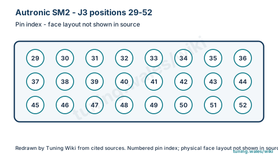
Select a pin in a photograph or the index to highlight it.
| Pin | Function / cavity | Confidence / source | Notes |
|---|---|---|---|
| Auxiliary 2 analogue input Cavity: Populated |
Confirmed Autronic SM2WR105 rev 001 |
||
| Auxiliary 4 analogue input Cavity: Populated |
Confirmed Autronic SM2WR105 rev 001 |
||
| Auxiliary 1 analogue input Cavity: Populated |
Confirmed Autronic SM2WR105 rev 001 |
||
| Auxiliary 3 analogue input Cavity: Populated |
Confirmed Autronic SM2WR105 rev 001 |
||
| Auxiliary analogue input ground Cavity: Populated |
Confirmed Autronic SM2WR105 rev 001 |
||
| Trigger supply Cavity: Populated |
Confirmed Autronic SM2WR105 rev 001 |
||
| Trigger ground Cavity: Populated |
Confirmed Autronic SM2WR105 rev 001 |
||
| Reference trigger input Cavity: Populated |
Confirmed Autronic SM2WR105 rev 001 |
||
| Cylinder pulse trigger input Cavity: Populated |
Confirmed Autronic SM2WR105 rev 001 |
||
| Spare speed input (turbo tachometer) Cavity: Populated |
Confirmed Autronic SM2WR105 rev 001 |
||
| Vehicle speed input Cavity: Populated |
Confirmed Autronic SM2WR105 rev 001 |
||
| Switch 1 input (A/C request / traction control enable) Cavity: Populated |
Confirmed Autronic SM2WR105 rev 001 |
||
| Switch 2 input (boost curve select) Cavity: Populated |
Confirmed Autronic SM2WR105 rev 001 |
||
| Unknown function Cavity: Unknown |
Unknown Autronic SM2WR105 rev 001 |
||
| Unknown function Cavity: Unknown |
Unknown Autronic SM2WR105 rev 001 |
||
| Ignition output ground Cavity: Populated |
Confirmed Autronic SM2WR105 rev 001 |
||
| Relay 1 output (fuel pump) Cavity: Populated |
Confirmed Autronic SM2WR105 rev 001 |
||
| Ignition 1 output Cavity: Populated |
Confirmed Autronic SM2WR105 rev 001 |
||
| Relay 2 output (A/C request) Cavity: Populated |
Confirmed Autronic SM2WR105 rev 001 |
||
| Ignition 2 output Cavity: Populated |
Confirmed Autronic SM2WR105 rev 001 |
||
| Relay 3 output (main cooling fan) Cavity: Populated |
Confirmed Autronic SM2WR105 rev 001 |
||
| Ignition 3 output Cavity: Populated |
Confirmed Autronic SM2WR105 rev 001 |
||
| Relay 4 output (auxiliary cooling fan) Cavity: Populated |
Confirmed Autronic SM2WR105 rev 001 |
||
| Ignition 4 output Cavity: Populated |
Confirmed Autronic SM2WR105 rev 001 |