The AEM EMS Series 2 30-6040 is an application-specific plug-in engine management system. It uses the vehicle connector assignments shown in its own manufacturer installation manual; other Series 2 part numbers must not be assumed to share this schedule.
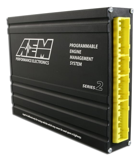
Applications and identification
The manufacturer’s manual identifies 1992–1995 Civic, Del Sol and Integra, and 1990–1995 Accord and Prelude (2.1 L only). Confirm exact engine, transmission and connector against the manual; the manufacturer’s product listing specifies manual transmission.
Connector pin assignments
The following tables transcribe the connector schedule in the AEM 30-6040 installation manual, PDF pages 8, 9, 10. The manufacturer labels each position with its original vehicle function and its EMS function, I/O direction and notes. Follow the connector diagram and viewing orientation in that manual. A dash reflects the manufacturer’s entry and does not by itself establish an unused or safe connection. Where a channel is configurable, its actual use also depends on the wiring and calibration.
Connector A
| Pin | Original vehicle function | AEM EMS function | I/O | Manufacturer notes |
|---|---|---|---|---|
| A1 | Injector 1 | Injector 1 | Output | PnP for Injector 1 |
| A2 | Injector 4 | Injector 4 | Output | PnP for Injector 4 |
| A3 | Injector 2 | Injector 2 | Output | PnP for Injector 2 |
| A4 | VTEC Solenoid Valve | High Side Driver 1 | Output | PnP for VTEC Solenoid |
| A5 | Injector 3 | Injector 3 | Output | PnP for Injector 3 |
| A6 | Primary 02 Heater Control | Injector 6 | Output | Avail, Injector Gnd, 1.5A max |
| A7 | Fuel Pump Relay | Low Side Driver 11 | Output | PnP for Fuel Pump Relay |
| A8 | Fuel Pump Relay (Accord/Prelude Only) | Injector 5 | Output | Avail, Injector Gnd, 1.5A max |
| A9 | Idle Air Control Valve | PW 1 | Output | PnP for Idle Air Control Valve |
| A10 | --- | Low Side Driver 2 | Output | Avail, Switched Gnd, 1.5A max |
| A11 | EGR Solenoid (Accord/Prelude Only) | Injector 10 | Output | Avail, Injector Gnd, 1.5A max |
| A12 | Radiator Fan Control (Except Prelude) | Low Side Driver 12 | Output | PnP for Radiator Fan |
| A13 | Malfunction Indicator Light | Low Side Driver 10 | Output | Avail, Switched Gnd, 1.5A max |
| A14 | --- | Injector 8 | Output | Avail, Injector Gnd, 1.5A max |
| A15 | A/C Clutch Relay | Low Side Driver 6 | Output | PnP for A/C Clutch Relay |
| A16 | Alternator Control (Except Accord/Prelude) | Injector 7 | Output | Avail, Injector Gnd, 1.5A max |
| A17 | IAB Control Solenoid (Accord/Integra Only) | Idle #2 | Output | Avail, Ground / +12V, 1.5A max |
| A18 | --- | Low Side Driver 8 | Output | Avail, Switched Gnd, 1.5A max |
| A19 | --- | Idle #4 | Output | Avail, Ground / +12V, 1.5A max |
| A20 | EVAP Purge Control Solenoid | Low Side Driver 4 | Output | Avail, Switched Gnd, 1.5A max |
| A21 | Ignition Control Module | Coil 1 | Output | PnP for Ignition Control Module (12/0V Rising edge) |
| A22 | Ignition Control Module | CAN1L | --- | Dedicated |
| A23 | Power Ground 1 | Power Ground | Both | Dedicated |
| A24 | Power Ground 2 | Power Ground | Both | Dedicated |
| A25 | Power Source 1 | +12V Switched | Both | Dedicated |
| A26 | Logic Ground 1 | Power Ground | Both | Dedicated |
Connector B
| Pin | Original vehicle function | AEM EMS function | I/O | Manufacturer notes |
|---|---|---|---|---|
| B1 | Power Source 2 | +12V Switched | Both | Dedicated |
| B2 | Logic Ground 2 | Power Ground | Both | Dedicated |
| B3 | --- | Coil 3 | Output | Avail, Rising Edge Trigger Coil Out |
| B4 | --- | Coil 4 | Output | Avail, Rising Edge Trigger Coil Out |
| B5 | A/C Switch Signal | Switch 3 | Input | PnP for A/C Switch Signal |
| B6 | --- | Coil 2 | Output | Avail, Rising Edge Trigger Coil Out |
| B7 | --- | ADCR13 | Input | Avail, 0–5 Volt Input, 100k pull up |
| B8 | Power Steering Pressure Switch | Switch 5 | Output | Avail, Switched Input |
| B9 | Starter Switch Signal | +12V When Cranking | Input | Dedicated |
| B10 | Vehicle Speed Sensor | T3 (Vehicle Speed) | Input | PnP for Vehicle Speed Sensor |
| B11 | CYP + | Cam Sensor | Input | Dedicated, PnP 1 pulse per cycle |
| B12 | CYP - | Timing Ground | Output | Dedicated |
| B13 | TDC + | T4 (Spare Speed) | Input | Avail, Magnetic Speed Sensor |
| B14 | TDC - | Timing Ground | Output | Dedicated |
| B15 | CKP + | Crank Sensor | Input | Dedicated, PnP 24 pulses per cycle |
| B16 | CKP- | Timing Ground | Output | Dedicated |
Connector C
| Pin | Original vehicle function | AEM EMS function | I/O | Manufacturer notes |
|---|---|---|---|---|
| C1 | --- | +12V Switched | Input | Dedicated |
| C2 | --- | CAN1H | --- | Dedicated |
| C3 | --- | Tach Output (LS7) | Output | Avail, Switched Gnd, 1.5A max |
| C4 | --- | Low Side Driver 9 | Output | Avail, Switched Gnd, 1.5A max |
| C5 | --- | Switch 6 | Input | Avail, Switched Input |
| C6 | --- | Low Side Driver 1 | Output | Avail, Switched Gnd, 1.5A max |
| C7 | --- | Switch 1 | Input | Avail, Switched Input |
| C8 | --- | IDLE #3 | Output | Avail, Ground / +12V, 1.5A max |
| C9 | --- | ADCR14 | Input | Avail, 0–5 Volt Input, 100k pull up |
| C10 | --- | PW 2 | Output | Avail, Boost Control Solenoid |
| C11 | --- | High Side Driver 2 | Output | Avail, +12V, 1.5A max |
| C12 | --- | Switch 2 | Input | Avail, Switched Input |
Connector D
| Pin | Original vehicle function | AEM EMS function | I/O | Manufacturer notes |
|---|---|---|---|---|
| D1 | Voltage Back Up | Permanent +12V | Input | Dedicated |
| D2 | Brake Switch (Except Prelude) | EGT 2 | Input | Avail, jumper set for 0–5V Input |
| D3 | Knock 1 | Knock 1 | Input | Dedicated |
| D4 | Service Check Connector | Injector 9 | Input | Avail, Injector Gnd, 1.5A max |
| D5 | --- | EGT 1 | Input | Avail, jumper set for 0–5V Input |
| D6 | VTEC Pressure Switch | Switch 4 | Input | Avail, Switched Input |
| D7 | Data Link Connector | High Side Driver 1 | Output | Avail, same as pin A4 |
| D8 | --- | MAF | Input | Avail, 0–5 Volt Input, 100k pull up |
| D9 | Alternator FR Signal | EGT 3 | Input | Avail, jumper set for 0–5V Input |
| D10 | Electronic Load Detector | EGT 4 | Input | Avail, jumper set for 0–5V Input |
| D11 | Throttle Position Sensor | TPS | Input | Dedicated |
| D12 | EGR Valve Lift Sensor (Accord/Prelude Only) | ADCR11 | Input | Avail, 0–5 Volt Input, 100k pull up |
| D13 | Engine Coolant Sensor | Coolant | Input | Dedicated, 2.2k pull up |
| D14 | Primary 02 Sensor | Lambda 1 | Input | Available, 0–5V Lambda 1 input |
| D15 | Inlet Air Temp Sensor | AIT | Input | Dedicated, 2.2k pull up |
| D16 | Secondary 02 Sensor | Lambda 2 | Input | Available, 0–5V Lambda 2 input |
| D17 | Map Sensor | MAP | Input | Dedicated |
| D18 | Shift Up Indicator Light (D15 only) | IDLE #1 | Output | Avail, Ground / +12V, 1.5A max |
| D19 | Sensor Voltage 1 | +5V Sensor | Output | Dedicated |
| D20 | Sensor Voltage 2 | +5V Sensor | Output | Dedicated |
| D21 | Sensor Ground 1 | Sensor Ground | Output | Dedicated, sensors only |
| D22 | Sensor Ground 2 | Sensor Ground | Output | Dedicated, sensors only |
Documentation
AEM 30-6040 Series 2 installation instructions and wiring chart. AEM engine management support archive.