The Adaptronic e420c standalone ECU is wired through four harness connectors: J1 (8-way) for power, ground and the four injector outputs; J2 (6-way) for the four high-current auxiliary outputs; J3 (20-way) for sensor and digital inputs; and J4 (16-way) for crank/cam triggers, ignition outputs, vehicle-speed inputs and the four low-current auxiliary outputs. This reference covers all 50 positions as drawn in Adaptronic's e420c wiring diagram of 15 June 2009, a manufacturer document.
Orientation and numbering
The Adaptronic drawing shows every connector from the wiring side, not the pin side, and advises confirming the wire colours. J1 and J2 are single rows numbered from 1 at the top. J3 positions carry an A prefix in two columns (A20 to A11 on the left, A10 to A1 on the right, top to bottom); J4 positions carry a B prefix (B16 to B9 left, B8 to B1 right). The redrawn diagrams follow the same arrangement; spacing is schematic.
Trigger input options
J4 provides two alternative trigger wiring schemes. Option 1 uses digital (Hall or optical) crank/cam sensors on B13, B5 and B12; option 2 uses reluctor sensors on B11, B3 and B10. B4 is the crank-angle-sensor ground and shield. The drawing shows the digital option 1 sensor ground taken either from the ECU (option 1a) or from vehicle ground (option 1b).
Output limits and cautions
J2 auxiliary outputs 1–4 are rated for loads up to 3 A inductive or 7 A resistive, and the drawing calls for a chassis ground on J2 for high-current use. Auxiliary outputs 5–8 on J4 are rated up to 300 mA. The digital inputs on J3 are internally pulled up and 12 V tolerant. The e420c has no built-in igniter: ignition outputs B2, B9 and B1 must drive a separate igniter or transistor and must not be connected directly to ignition coils.
Diagram redrawn by Tuning Wiki from the Adaptronic e420c wiring diagram (2009).
Not established
Connector housing part numbers, the physical cavity pitch, and whether other e420c hardware builds use the same assignment are not stated in the cited drawing.
Sources
- Wiring diagram for Adaptronic e420c ECU. Andy Wyatt, Adaptronic; manufacturer wiring diagram dated 15 June 2009, hosted as a forum attachment on MiataTurbo.net; connectors viewed from the wiring side. Accessed 19 November 2026.
Connector pinout
Adaptronic e420c as drawn in the manufacturer wiring diagram dated 15 June 2009 (Andy Wyatt, Adaptronic). Manufacturer documentation; the drawing advises confirming wire colours, and earlier or later hardware builds are not covered by this source.
View orientation is stated beside each photograph. Unknown functions remain in the pin index.
J1 (8-way, power, ground and injectors)
View: Viewed from the wiring side (not the pin side), as stated on the 2009 Adaptronic drawing; cavity spacing schematic.

Select a pin in a photograph or the index to highlight it.
| Pin | Function / cavity | Confidence / source | Notes |
|---|---|---|---|
| +12 V ignition Cavity: Populated |
Confirmed Adaptronic e420c drawing 2009-06-15 |
Wire colour: Red. | |
| Ground Cavity: Populated |
Confirmed Adaptronic e420c drawing 2009-06-15 |
Wire colour: Black. | |
| Ground Cavity: Populated |
Confirmed Adaptronic e420c drawing 2009-06-15 |
Wire colour: Black. | |
| Ground Cavity: Populated |
Confirmed Adaptronic e420c drawing 2009-06-15 |
Wire colour: Black. | |
| Injector 1 Cavity: Populated |
Confirmed Adaptronic e420c drawing 2009-06-15 |
Wire colour: Purple. | |
| Injector 2 Cavity: Populated |
Confirmed Adaptronic e420c drawing 2009-06-15 |
Wire colour: White. | |
| Injector 3 Cavity: Populated |
Confirmed Adaptronic e420c drawing 2009-06-15 |
Wire colour: Pink. | |
| Injector 4 Cavity: Populated |
Confirmed Adaptronic e420c drawing 2009-06-15 |
Wire colour: Grey. |
J2 (6-way, auxiliary outputs 1-4)
View: Viewed from the wiring side (not the pin side), as stated on the 2009 Adaptronic drawing; cavity spacing schematic.

Select a pin in a photograph or the index to highlight it.
| Pin | Function / cavity | Confidence / source | Notes |
|---|---|---|---|
| Auxiliary output 1 Cavity: Populated |
Confirmed Adaptronic e420c drawing 2009-06-15 |
Wire colour: Brown; up to 3 A inductive / 7 A resistive. | |
| Auxiliary output 2 Cavity: Populated |
Confirmed Adaptronic e420c drawing 2009-06-15 |
Wire colour: Red; up to 3 A inductive / 7 A resistive. | |
| Auxiliary output 3 Cavity: Populated |
Confirmed Adaptronic e420c drawing 2009-06-15 |
Wire colour: Green; up to 3 A inductive / 7 A resistive. | |
| Auxiliary output 4 Cavity: Populated |
Confirmed Adaptronic e420c drawing 2009-06-15 |
Wire colour: Blue; up to 3 A inductive / 7 A resistive. | |
| Ground Cavity: Populated |
Confirmed Adaptronic e420c drawing 2009-06-15 |
Wire colour: Black; chassis ground required for high-current applications. | |
| Ground Cavity: Populated |
Confirmed Adaptronic e420c drawing 2009-06-15 |
Wire colour: Black. |
J3 (20-way, sensor and digital inputs)
View: Viewed from the wiring side (not the pin side), as stated on the 2009 Adaptronic drawing; cavity spacing schematic.

Select a pin in a photograph or the index to highlight it.
| Pin | Function / cavity | Confidence / source | Notes |
|---|---|---|---|
| Digital input 8 Cavity: Populated |
Confirmed Adaptronic e420c drawing 2009-06-15 |
Wire colour: Orange/red. Digital inputs are internally pulled up and 12 V tolerant. | |
| Digital input 6 Cavity: Populated |
Confirmed Adaptronic e420c drawing 2009-06-15 |
Wire colour: Red/green. Digital inputs are internally pulled up and 12 V tolerant. | |
| Digital input 4 Cavity: Populated |
Confirmed Adaptronic e420c drawing 2009-06-15 |
Wire colour: Red/brown. Digital inputs are internally pulled up and 12 V tolerant. | |
| Digital input 2 Cavity: Populated |
Confirmed Adaptronic e420c drawing 2009-06-15 |
Wire colour: Pink. Digital inputs are internally pulled up and 12 V tolerant. | |
| External input Cavity: Populated |
Confirmed Adaptronic e420c drawing 2009-06-15 |
Wire colour: Grey. | |
| EGO (oxygen sensor) Cavity: Populated |
Confirmed Adaptronic e420c drawing 2009-06-15 |
Wire colour: Black shielded core or yellow/red. | |
| Manifold air temperature Cavity: Populated |
Confirmed Adaptronic e420c drawing 2009-06-15 |
Wire colour: Blue. | |
| MAP +5 V Cavity: Populated |
Confirmed Adaptronic e420c drawing 2009-06-15 |
Wire colour: Yellow. | |
| MAP ground Cavity: Populated |
Confirmed Adaptronic e420c drawing 2009-06-15 |
Wire colour: Brown. | |
| TPS signal Cavity: Populated |
Confirmed Adaptronic e420c drawing 2009-06-15 |
Wire colour: Green. | |
| Digital input 7 Cavity: Populated |
Confirmed Adaptronic e420c drawing 2009-06-15 |
Wire colour: Orange/black. Digital inputs are internally pulled up and 12 V tolerant. | |
| Digital input 5 Cavity: Populated |
Confirmed Adaptronic e420c drawing 2009-06-15 |
Wire colour: Red/blue. Digital inputs are internally pulled up and 12 V tolerant. | |
| Digital input 3 Cavity: Populated |
Confirmed Adaptronic e420c drawing 2009-06-15 |
Wire colour: Red/black. Digital inputs are internally pulled up and 12 V tolerant. | |
| Digital input 1 Cavity: Populated |
Confirmed Adaptronic e420c drawing 2009-06-15 |
Wire colour: White. Digital inputs are internally pulled up and 12 V tolerant. | |
| Knock input Cavity: Populated |
Confirmed Adaptronic e420c drawing 2009-06-15 |
Wire colour: Grey shielded core or yellow/green. | |
| Auxiliary temperature Cavity: Populated |
Confirmed Adaptronic e420c drawing 2009-06-15 |
Wire colour: Violet. | |
| Water temperature Cavity: Populated |
Confirmed Adaptronic e420c drawing 2009-06-15 |
Wire colour: Yellow/black. | |
| MAP signal Cavity: Populated |
Confirmed Adaptronic e420c drawing 2009-06-15 |
Wire colour: Orange. | |
| TPS +5 V Cavity: Populated |
Confirmed Adaptronic e420c drawing 2009-06-15 |
Wire colour: Red. | |
| TPS ground Cavity: Populated |
Confirmed Adaptronic e420c drawing 2009-06-15 |
Wire colour: Black. |
J4 (16-way, triggers, ignition and auxiliaries)
View: Viewed from the wiring side (not the pin side), as stated on the 2009 Adaptronic drawing; cavity spacing schematic.
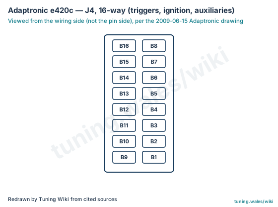
Select a pin in a photograph or the index to highlight it.
| Pin | Function / cavity | Confidence / source | Notes |
|---|---|---|---|
| Ignition 3 / tacho Cavity: Populated |
Confirmed Adaptronic e420c drawing 2009-06-15 |
Wire colour: Blue. | |
| Ignition 1 Cavity: Populated |
Confirmed Adaptronic e420c drawing 2009-06-15 |
Wire colour: Yellow; drives an external igniter, not a coil. | |
| Reluctor input 2 (option 2) Cavity: Populated |
Confirmed Adaptronic e420c drawing 2009-06-15 |
Wire colour: Red internal. | |
| CAS ground Cavity: Populated |
Confirmed Adaptronic e420c drawing 2009-06-15 |
Wire colour: White internal and shield. | |
| Digital crank/cam input 2 (option 1) Cavity: Populated |
Confirmed Adaptronic e420c drawing 2009-06-15 |
Wire colour: Red internal. | |
| Secondary VSS Cavity: Populated |
Confirmed Adaptronic e420c drawing 2009-06-15 |
Wire colour: Orange; internal pull-up. | |
| Auxiliary output 8 Cavity: Populated |
Confirmed Adaptronic e420c drawing 2009-06-15 |
Wire colour: Red/blue; up to 300 mA. | |
| Auxiliary output 6 Cavity: Populated |
Confirmed Adaptronic e420c drawing 2009-06-15 |
Wire colour: Red/brown; up to 300 mA. | |
| Ignition 2 Cavity: Populated |
Confirmed Adaptronic e420c drawing 2009-06-15 |
Wire colour: Green; drives an external igniter, not a coil. | |
| Reluctor input 3 (option 2) Cavity: Populated |
Confirmed Adaptronic e420c drawing 2009-06-15 |
Wire colour: Yellow internal. | |
| Reluctor input 1 (option 2) Cavity: Populated |
Confirmed Adaptronic e420c drawing 2009-06-15 |
Wire colour: Black internal. | |
| Digital crank/cam input 3 (option 1) Cavity: Populated |
Confirmed Adaptronic e420c drawing 2009-06-15 |
Wire colour: Yellow internal. | |
| Digital crank/cam input 1 (option 1) Cavity: Populated |
Confirmed Adaptronic e420c drawing 2009-06-15 |
Wire colour: Black internal. | |
| Master VSS Cavity: Populated |
Confirmed Adaptronic e420c drawing 2009-06-15 |
Wire colour: Brown; internal pull-up. | |
| Auxiliary output 7 Cavity: Populated |
Confirmed Adaptronic e420c drawing 2009-06-15 |
Wire colour: Red/green; up to 300 mA. | |
| Auxiliary output 5 Cavity: Populated |
Confirmed Adaptronic e420c drawing 2009-06-15 |
Wire colour: Red/black; up to 300 mA. |