What is D-Jetronic?
Bosch D-Jetronic is an early electronically controlled, intermittent port-injection system. Bosch lists its 1967 introduction on the VW 1600 E. Unlike K- and KE-Jetronic, its main injectors are solenoid valves opened in electrical pulses. Its ECU uses analogue electronic circuitry to determine injection duration; it is not a modern digital, map-based ECU. [1, 2]
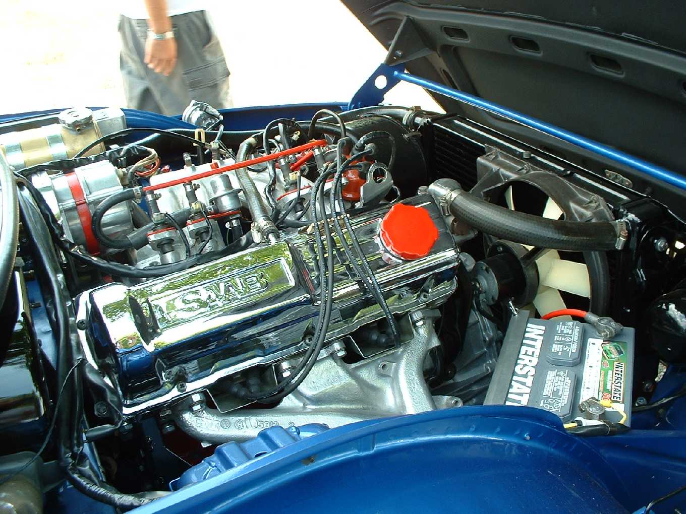

How it works
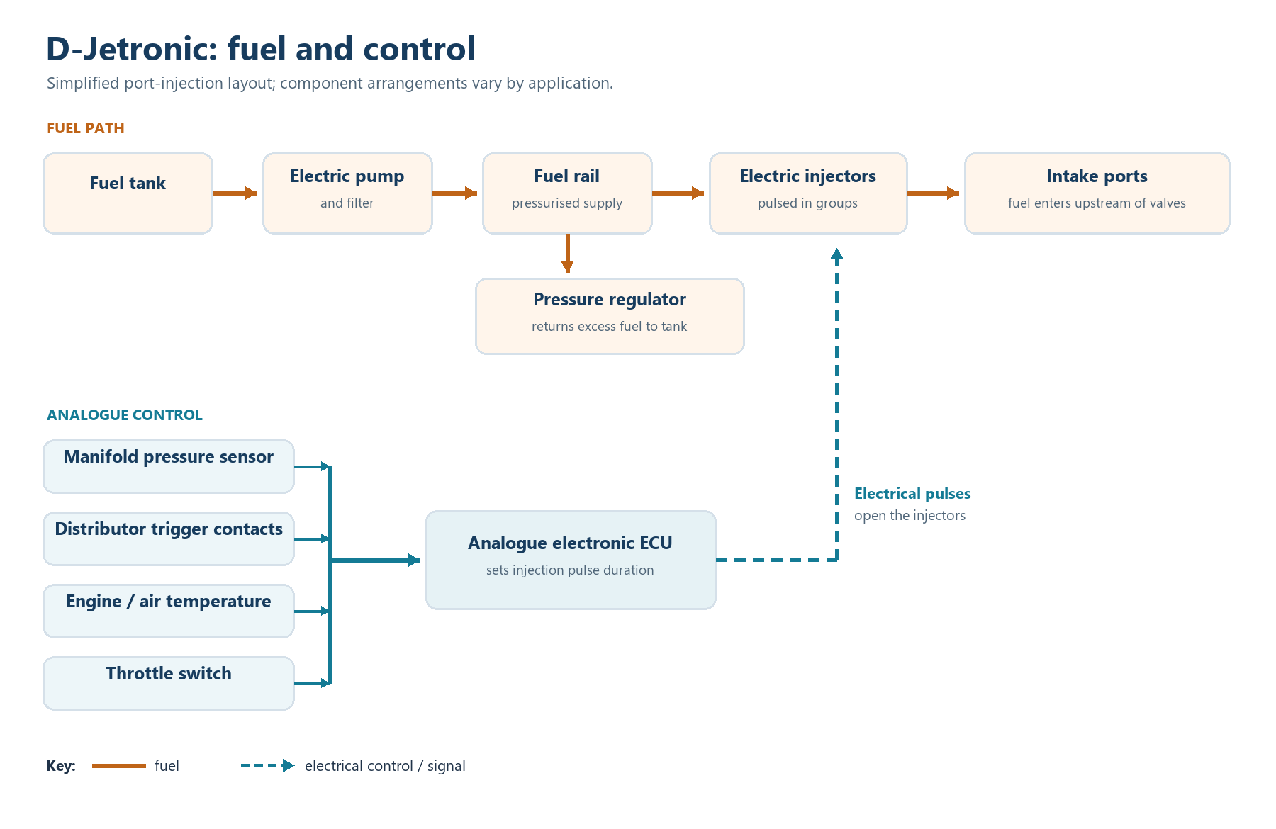
- An electric pump and filter supply a common fuel distribution pipe or rail. A pressure regulator controls fuel pressure and returns surplus fuel to the tank.
- A manifold-pressure sensor connected to the intake manifold supplies the main engine-load information. Distributor trigger contacts provide engine-speed and injection-trigger information.
- The ECU combines these inputs with corrections such as engine and intake-air temperature and throttle-switch signals. It produces electrical injection pulses whose duration varies with operating conditions.
- The electrically operated injectors spray fuel into the intake ports. In the documented four-cylinder VW-Porsche example, they operate in two pairs rather than as individually timed sequential injectors. [2]
The analogue pressure sensor and ECU
The pressure sensor is connected to the manifold by a hose. Its pressure-sensitive internal elements move an armature in a coil assembly, changing inductance in the ECU's analogue circuit; it is not simply a modern three-wire voltage-output MAP sensor. Designs and calibration differ, so match the sensor to the engine and ECU rather than assuming similar-looking parts interchange. [4]
The original system determines fuel from its inputs without the lambda-sensor feedback loop found on later closed-loop systems. An auxiliary-air device and, on documented installations, a separate electrically operated cold-start valve support cold running and starting. The exact control and components differ by model. [3, 2]
What kind of injectors?
D-Jetronic's main injectors are electromagnetic port injectors. The ECU energises each group of injector coils to lift the valves; fuel pressure forces fuel through while they are open. At the specified regulated pressure, the length of the pulse is a major determinant of the delivered quantity. The separate cold-start valve should not be confused with the main injector set. [2]
By comparison, K-Jetronic and KE-Jetronic meter fuel in a distributor and use pressure-opening continuous-spray main injectors. The presence of an electronic ECU does not by itself tell you which kind of injector is fitted.
Identification and workshop checks
- Identify the engine, ECU, pressure sensor and injector part numbers as a matched application. A manifold hose leading to a separate pressure sensor, distributor trigger contacts and electrical injector connectors are useful clues.
- Check fuel hoses, leaks, pump supply and regulated pressure against the correct vehicle specification. Injector condition, leaks, spray and electrical connections affect fuel delivery; use the appropriate injector-testing procedure.
- Inspect the pressure-sensor hose and connections, engine and air temperature sensors, throttle switch, distributor trigger contacts, wiring, grounds and relays. Follow the correct manual's test conditions and limits.
- Do not turn sealed pressure-sensor adjustments as a first response to poor running. The sensor's calibration is application-specific; check for other faults and use a specialist procedure if it needs assessment.
Follow the applicable procedure to release fuel pressure before opening a line. The source-linked Bosch teaching sheet below provides a labelled visual layout.
Sources and further pictures
- [1] Bosch Classic: spare parts brochure, Jetronic history and components.
- [2] Bosch D-Jetronic workshop manual, VW-Porsche 914, independent reproduction; system description, paired injectors and test charts. The described details are specific to that installation.
- [3] Bosch Classic: D-Jetronic teaching diagram, labelled system and air-cooled-engine layouts.
- [4] Dr-DJet: manifold pressure sensor, specialist description and photographs of sensor construction; application and calibration information should be checked against the relevant vehicle manual.
- Bosch historical photograph of an early Jetronic control-unit circuit board. Accessed 10 November 2026.